
Service Manual

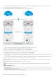

Table Of Contents
- Dell Configuration Guide for the S6100–ON System 9.14.2.5
- About this Guide
- Configuration Fundamentals
- Getting Started
- Management
- Configuring Privilege Levels
- Configuring Logging
- Log Messages in the Internal Buffer
- Disabling System Logging
- Sending System Messages to a Syslog Server
- Track Login Activity
- Limit Concurrent Login Sessions
- Enabling Secured CLI Mode
- Changing System Logging Settings
- Display the Logging Buffer and the Logging Configuration
- Configuring a UNIX Logging Facility Level
- Synchronizing Log Messages
- Enabling Timestamp on Syslog Messages
- File Transfer Services
- Terminal Lines
- Setting Timeout for EXEC Privilege Mode
- Using Telnet to get to Another Network Device
- Lock CONFIGURATION Mode
- LPC Bus Quality Degradation
- Restoring the Factory Default Settings
- Reloading the system
- Viewing the Reason for Last System Reboot
- 802.1X
- Port-Authentication Process
- Configuring 802.1X
- Important Points to Remember
- Enabling 802.1X
- Configuring dot1x Profile
- Configuring MAC addresses for a do1x Profile
- Configuring the Static MAB and MAB Profile
- Configuring Critical VLAN
- Configuring Request Identity Re-Transmissions
- Configuring a Quiet Period after a Failed Authentication
- Forcibly Authorizing or Unauthorizing a Port
- Re-Authenticating a Port
- Configuring Dynamic VLAN Assignment with Port Authentication
- Guest and Authentication-Fail VLANs
- Multi-Host Authentication
- Multi-Supplicant Authentication
- MAC Authentication Bypass
- Dynamic CoS with 802.1X
- Access Control List (ACL) VLAN Groups and Content Addressable Memory (CAM)
- Access Control Lists (ACLs)
- IP Access Control Lists (ACLs)
- Important Points to Remember
- IP Fragment Handling
- Configure a Standard IP ACL
- Configure an Extended IP ACL
- Configure Layer 2 and Layer 3 ACLs
- Assign an IP ACL to an Interface
- Applying an IP ACL
- Configure Ingress ACLs
- Configure Egress ACLs
- IP Prefix Lists
- ACL Remarks
- ACL Resequencing
- Route Maps
- Bidirectional Forwarding Detection (BFD)
- Border Gateway Protocol (BGP)
- BGP IP version 4 (BGPv4) Overview
- Basic BGP configuration tasks
- Advanced BGP configuration tasks
- Route-refresh and Soft-reconfiguration
- Aggregating Routes
- Filtering BGP
- Configuring BGP Fast Fall-Over
- Configuring Passive Peering
- Enabling Graceful Restart
- Redistributing Routes
- Enabling Additional Paths
- Configuring IP Community Lists
- Configuring an IP Extended Community List
- Configure BGP attributes
- Enabling Multipath
- Route Reflectors
- Enabling Route Flap Dampening
- Changing BGP keepalive and hold timers
- Setting the extended timer
- Enabling or disabling BGP neighbors
- Route Map Continue
- Configuring BGP Confederations
- Configuring a BGP VRF address family
- Maintaining Existing AS Numbers During an AS Migration
- Allowing an AS Number to Appear in its Own AS Path
- Enabling MBGP Configurations
- MBGP support for IPv6
- Configuring IPv6 MBGP between peers
- Example-Configuring IPv4 and IPv6 neighbors
- Configure IPv6 NH Automatically for IPv6 Prefix Advertised over IPv4 Neighbor
- BGP Regular Expression Optimization
- Debugging BGP
- Content Addressable Memory (CAM)
- Control Plane Policing (CoPP)
- Data Center Bridging (DCB)
- Ethernet Enhancements in Data Center Bridging
- Enabling Data Center Bridging
- Data Center Bridging: Default Configuration
- Configuring Priority-Based Flow Control
- Configuring PFC in a DCB Map
- Applying a DCB Map on a Port
- Configuring PFC without a DCB Map
- Configuring PFC Asymmetric
- Priority-Based Flow Control Using Dynamic Buffer Method
- Shared headroom for lossless or PFC packets
- Behavior of Tagged Packets
- SNMP Support for PFC and Buffer Statistics Tracking
- Performing PFC Using DSCP Bits Instead of 802.1p Bits
- Configuration Example for DSCP and PFC Priorities
- Using PFC to Manage Converged Ethernet Traffic
- Generation of PFC for a Priority for Untagged Packets
- Configure Enhanced Transmission Selection
- Hierarchical Scheduling in ETS Output Policies
- Using ETS to Manage Converged Ethernet Traffic
- Applying DCB Policies in a Switch Stack
- Configure a DCBx Operation
- Verifying the DCB Configuration
- QoS dot1p Traffic Classification and Queue Assignment
- Configuring the Dynamic Buffer Method
- Sample DCB Configuration
- Dynamic Host Configuration Protocol (DHCP)
- DHCP Packet Format and Options
- Assign an IP Address using DHCP
- Implementation Information
- Configure the System to be a DHCP Server
- Configure the System to be a DHCP Client
- DHCP Relay When DHCP Server and Client are in Different VRFs
- Non-default VRF configuration for DHCPv6 helper address
- Configuring DHCP relay source interface
- Configure the System for User Port Stacking (Option 230)
- Configure Secure DHCP
- Option 82 (DHCPv4 relay options)
- DHCPv6 relay agent options
- DHCP Snooping
- Enabling DHCP Snooping
- Enabling IPv6 DHCP Snooping
- Adding a Static Entry in the Binding Table
- Adding a Static IPV6 DHCP Snooping Binding Table
- Clearing the Binding Table
- Clearing the DHCP IPv6 Binding Table
- Displaying the Contents of the Binding Table
- Displaying the Contents of the DHCPv6 Binding Table
- Debugging the IPv6 DHCP
- IPv6 DHCP Snooping MAC-Address Verification
- Drop DHCP Packets on Snooped VLANs Only
- Dynamic ARP Inspection
- Configuring Dynamic ARP Inspection
- Source Address Validation
- Equal Cost Multi-Path (ECMP)
- FIP Snooping
- Fibre Channel over Ethernet
- Ensure Robustness in a Converged Ethernet Network
- FIP Snooping on Ethernet Bridges
- Using FIP Snooping
- FIP Snooping Prerequisites
- Important Points to Remember
- Enabling the FCoE Transit Feature
- Enable FIP Snooping on VLANs
- Configure the FC-MAP Value
- Configure a Port for a Bridge-to-Bridge Link
- Configure a Port for a Bridge-to-FCF Link
- Impact on Other Software Features
- FIP Snooping Restrictions
- Configuring FIP Snooping
- Displaying FIP Snooping Information
- FCoE Transit Configuration Example
- Flex Hash and Optimized Boot-Up
- Force10 Resilient Ring Protocol (FRRP)
- GARP VLAN Registration Protocol (GVRP)
- Internet Group Management Protocol (IGMP)
- IGMP Protocol Overview
- Configure IGMP
- Viewing IGMP Enabled Interfaces
- Selecting an IGMP Version
- Viewing IGMP Groups
- Adjusting Timers
- Enabling IGMP Immediate-Leave
- IGMP Snooping
- Fast Convergence after MSTP Topology Changes
- Egress Interface Selection (EIS) for HTTP and IGMP Applications
- Designating a Multicast Router Interface
- Interfaces
- Interface Types
- View Basic Interface Information
- Resetting an Interface to its Factory Default State
- Enabling a Physical Interface
- Physical Interfaces
- Automatic recovery of an Err-disabled interface
- Egress Interface Selection (EIS)
- Management Interfaces
- VLAN Interfaces
- Loopback Interfaces
- Null Interfaces
- Configuring Port Delay
- Port Channel Interfaces
- Port Channel Definition and Standards
- Port Channel Benefits
- Port Channel Implementation
- Interfaces in Port Channels
- Configuration Tasks for Port Channel Interfaces
- Creating a Port Channel
- Adding a Physical Interface to a Port Channel
- Reassigning an Interface to a New Port Channel
- Configuring the Minimum Oper Up Links in a Port Channel
- Adding or Removing a Port Channel from a VLAN
- Assigning an IP Address to a Port Channel
- Deleting or Disabling a Port Channel
- Load Balancing Through Port Channels
- Load-Balancing Method
- Changing the Hash Algorithm
- Bulk Configuration
- Defining Interface Range Macros
- Monitoring and Maintaining Interfaces
- Split 40G Ports on a 16X40G QSFP+ Module
- Splitting 100G Ports
- Link Dampening
- Link Bundle Monitoring
- Using Ethernet Pause Frames for Flow Control
- Configure the MTU Size on an Interface
- Port-Pipes
- CR4 Auto-Negotiation
- FEC Configuration
- Setting the Speed of Ethernet Interfaces
- Syslog Warning Upon Connecting SFP28 Optics with QSA
- Adjusting the Keepalive Timer
- View Advanced Interface Information
- Configuring the Traffic Sampling Size Globally
- Dynamic Counters
- Enhanced Validation of Interface Ranges
- Compressing Configuration Files
- IPv4 Routing
- IP Addresses
- Configuration Tasks for IP Addresses
- Assigning IP Addresses to an Interface
- Configuring Static Routes
- Configure Static Routes for the Management Interface
- IPv4 Path MTU Discovery Overview
- Using the Configured Source IP Address in ICMP Messages
- Configuring the Duration to Establish a TCP Connection
- Enabling Directed Broadcast
- Resolution of Host Names
- Enabling Dynamic Resolution of Host Names
- Specifying the Local System Domain and a List of Domains
- Configuring DNS with Traceroute
- ARP
- Configuration Tasks for ARP
- Configuring Static ARP Entries
- Enabling Proxy ARP
- Clearing ARP Cache
- ARP Learning via Gratuitous ARP
- Enabling ARP Learning via Gratuitous ARP
- ARP Learning via ARP Request
- Configuring ARP Retries
- ICMP
- Configuration Tasks for ICMP
- Enabling ICMP Unreachable Messages
- ICMP Redirects
- UDP Helper
- Enabling UDP Helper
- Configurations Using UDP Helper
- UDP Helper with Broadcast-All Addresses
- UDP Helper with Subnet Broadcast Addresses
- UDP Helper with Configured Broadcast Addresses
- UDP Helper with No Configured Broadcast Addresses
- Troubleshooting UDP Helper
- IPv6 Routing
- Protocol Overview
- Implementing IPv6 with Dell EMC Networking OS
- ICMPv6
- Path MTU discovery
- IPv6 Neighbor Discovery
- Secure Shell (SSH) Over an IPv6 Transport
- Configuration Tasks for IPv6
- Adjusting Your CAM-Profile
- Assigning an IPv6 Address to an Interface
- Assigning a Static IPv6 Route
- Configuring Telnet with IPv6
- SNMP over IPv6
- Displaying IPv6 Information
- Displaying an IPv6 Interface Information
- Showing IPv6 Routes
- Showing the Running-Configuration for an Interface
- Clearing IPv6 Routes
- Disabling ND Entry Timeout
- Configuring IPv6 RA Guard
- iSCSI Optimization
- iSCSI Optimization Overview
- Monitoring iSCSI Traffic Flows
- Application of Quality of Service to iSCSI Traffic Flows
- Information Monitored in iSCSI Traffic Flows
- Detection and Auto-Configuration for Dell EqualLogic Arrays
- Configuring Detection and Ports for Dell Compellent Arrays
- Synchronizing iSCSI Sessions Learned on VLT-Lags with VLT-Peer
- Enable and Disable iSCSI Optimization
- Default iSCSI Optimization Values
- iSCSI Optimization Prerequisites
- Configuring iSCSI Optimization
- Displaying iSCSI Optimization Information
- iSCSI Optimization Overview
- Intermediate System to Intermediate System
- IS-IS Protocol Overview
- IS-IS Addressing
- Multi-Topology IS-IS
- Graceful Restart
- Implementation Information
- Configuration Information
- IS-IS Metric Styles
- Configure Metric Values
- Sample Configurations
- In-Service Software Upgrade
- Link Aggregation Control Protocol (LACP)
- Layer 2
- Manage the MAC Address Table
- MAC Learning Limit
- Setting the MAC Learning Limit
- mac learning-limit Dynamic
- mac learning-limit mac-address-sticky
- mac learning-limit station-move
- mac learning-limit no-station-move
- Learning Limit Violation Actions
- Setting Station Move Violation Actions
- Recovering from Learning Limit and Station Move Violations
- Disabling MAC Address Learning on the System
- Enabling port security
- NIC Teaming
- Configure Redundant Pairs
- Far-End Failure Detection
- Link Layer Discovery Protocol (LLDP)
- 802.1AB (LLDP) Overview
- Optional TLVs
- TIA-1057 (LLDP-MED) Overview
- Configure LLDP
- CONFIGURATION versus INTERFACE Configurations
- Enabling LLDP
- Enabling LLDP on Management Ports
- Advertising TLVs
- Storing and Viewing Unrecognized LLDP TLVs
- Viewing the LLDP Configuration
- Viewing Information Advertised by Adjacent LLDP Neighbors
- Configuring LLDPDU Intervals
- Configuring LLDP Notification Interval
- Configuring Transmit and Receive Mode
- Configuring the Time to Live Value
- Debugging LLDP
- Relevant Management Objects
- Microsoft Network Load Balancing
- Multicast Source Discovery Protocol (MSDP)
- Anycast RP
- Implementation Information
- Configure Multicast Source Discovery Protocol
- Enable MSDP
- Manage the Source-Active Cache
- Accept Source-Active Messages that Fail the RFP Check
- Specifying Source-Active Messages
- Limiting the Source-Active Messages from a Peer
- Preventing MSDP from Caching a Local Source
- Preventing MSDP from Caching a Remote Source
- Preventing MSDP from Advertising a Local Source
- Logging Changes in Peership States
- Terminating a Peership
- Clearing Peer Statistics
- Debugging MSDP
- MSDP with Anycast RP
- Configuring Anycast RP
- MSDP Sample Configurations
- Multicast Listener Discovery Protocol
- Multiple Spanning Tree Protocol (MSTP)
- Spanning Tree Variations
- Configure Multiple Spanning Tree Protocol
- Enable Multiple Spanning Tree Globally
- Adding and Removing Interfaces
- Creating Multiple Spanning Tree Instances
- Influencing MSTP Root Selection
- Interoperate with Non-Dell Bridges
- Changing the Region Name or Revision
- Modifying Global Parameters
- Modifying the Interface Parameters
- Setting STP path cost as constant
- Configuring an EdgePort
- Flush MAC Addresses after a Topology Change
- MSTP Sample Configurations
- Debugging and Verifying MSTP Configurations
- Multicast Features
- Object Tracking
- Open Shortest Path First (OSPFv2 and OSPFv3)
- Protocol Overview
- OSPF with Dell EMC Networking OS
- Configuration Information
- Configuration Task List for OSPFv2 (OSPF for IPv4)
- Enabling OSPFv2
- Assigning a Router ID
- Assigning an OSPFv2 Area
- Enable OSPFv2 on Interfaces
- Configuring Stub Areas
- Enabling Passive Interfaces
- Enabling Fast-Convergence
- Changing OSPFv2 Parameters on Interfaces
- Enabling OSPFv2 Authentication
- Enabling OSPFv2 Graceful Restart
- Creating Filter Routes
- Applying Prefix Lists
- Redistributing Routes
- Troubleshooting OSPFv2
- Sample Configurations for OSPFv2
- Configuration Task List for OSPFv2 (OSPF for IPv4)
- OSPFv3 NSSA
- Configuration Task List for OSPFv3 (OSPF for IPv6)
- Enabling IPv6 Unicast Routing
- Assigning IPv6 Addresses on an Interface
- Assigning Area ID on an Interface
- Assigning OSPFv3 Process ID and Router ID Globally
- Assigning OSPFv3 Process ID and Router ID to a VRF
- Applying cost for OSPFv3
- Configuring Stub Areas
- Configuring Passive-Interface
- Redistributing Routes
- Configuring a Default Route
- Applying cost for OSPFv3
- Enabling OSPFv3 Graceful Restart
- OSPFv3 Authentication Using IPsec
- Troubleshooting OSPFv3
- MIB Support for OSPFv3
- Policy-based Routing (PBR)
- PIM Sparse-Mode (PIM-SM)
- PIM Source-Specific Mode (PIM-SSM)
- Port Monitoring
- Important Points to Remember
- Port Monitoring
- Configuring Port Monitoring
- Configuring Monitor Multicast Queue
- Flow-Based Monitoring
- Remote Port Mirroring
- Encapsulated Remote Port Monitoring
- ERPM Behavior on a typical Dell EMC Networking OS
- Port Monitoring on VLT
- Private VLANs (PVLAN)
- Per-VLAN Spanning Tree Plus (PVST+)
- Protocol Overview
- Implementation Information
- Configure Per-VLAN Spanning Tree Plus
- Enabling PVST+
- Disabling PVST+
- Influencing PVST+ Root Selection
- Modifying Global PVST+ Parameters
- Modifying Interface PVST+ Parameters
- Configuring an EdgePort
- PVST+ in Multi-Vendor Networks
- Enabling PVST+ Extend System ID
- PVST+ Sample Configurations
- Quality of Service (QoS)
- Implementation Information
- Port-Based QoS Configurations
- Policy-Based QoS Configurations
- Enabling QoS Rate Adjustment
- Enabling Strict-Priority Queueing
- Queue Classification Requirements for PFC Functionality
- Support for marking dot1p value in L3 Input Qos Policy
- Weighted Random Early Detection
- Pre-Calculating Available QoS CAM Space
- Specifying Policy-Based Rate Shaping in Packets Per Second
- Configuring Policy-Based Rate Shaping
- Configuring Weights and ECN for WRED
- Configuring WRED and ECN Attributes
- Guidelines for Configuring ECN for Classifying and Color-Marking Packets
- Applying Layer 2 Match Criteria on a Layer 3 Interface
- Enabling Buffer Statistics Tracking
- Routing Information Protocol (RIP)
- Remote Monitoring (RMON)
- Rapid Spanning Tree Protocol (RSTP)
- Protocol Overview
- Configuring Rapid Spanning Tree
- Important Points to Remember
- Configuring Interfaces for Layer 2 Mode
- Enabling Rapid Spanning Tree Protocol Globally
- Adding and Removing Interfaces
- Modifying Global Parameters
- Modifying Interface Parameters
- Enabling SNMP Traps for Root Elections and Topology Changes
- Influencing RSTP Root Selection
- Configuring an EdgePort
- Configuring Fast Hellos for Link State Detection
- Software-Defined Networking (SDN)
- Security
- AAA Accounting
- AAA Authentication
- Obscuring Passwords and Keys
- AAA Authorization
- RADIUS
- RADIUS Authentication
- Configuration Task List for RADIUS
- Support for Change of Authorization and Disconnect Messages packets
- Change of Authorization (CoA) packets
- Disconnect Messages
- Attributes
- Error-cause Values
- CoA Packet Processing
- CoA or DM Discard
- Disconnect Message Processing
- Configuring DAC
- Configuring the port number
- Configuring shared key
- Disconnecting administrative users logged in through RADIUS
- Configuring CoA to bounce 802.1x enabled ports
- Configuring CoA to re-authenticate 802.1x sessions
- Terminating the 802.1x user session
- Disabling 802.1x enabled port
- Important points to remember
- Configuring replay protection
- Rate-limiting RADIUS packets
- Configuring time-out value
- TACACS+
- Protection from TCP Tiny and Overlapping Fragment Attacks
- Enabling SCP and SSH
- Using SCP with SSH to Copy a Software Image
- Removing the RSA Host Keys and Zeroizing Storage
- Configuring When to Re-generate an SSH Key
- Configuring the SSH Server Key Exchange Algorithm
- Configuring the HMAC Algorithm for the SSH Server
- Configuring the SSH Server Cipher List
- Configuring DNS in the SSH Server
- Secure Shell Authentication
- Troubleshooting SSH
- Telnet
- VTY Line and Access-Class Configuration
- Role-Based Access Control
- Two Factor Authentication (2FA)
- Configuring the System to Drop Certain ICMP Reply Messages
- SSH Lockout Settings
- Dell EMC Networking OS Security Hardening
- Service Provider Bridging
- sFlow
- Simple Network Management Protocol (SNMP)
- Protocol Overview
- Implementation Information
- SNMPv3 Compliance With FIPS
- Configuration Task List for SNMP
- Important Points to Remember
- Set up SNMP
- Reading Managed Object Values
- Writing Managed Object Values
- Configuring Contact and Location Information using SNMP
- Subscribing to Managed Object Value Updates using SNMP
- Enabling a Subset of SNMP Traps
- Enabling an SNMP Agent to Notify Syslog Server Failure
- Copy Configuration Files Using SNMP
- Copying a Configuration File
- Copying Configuration Files via SNMP
- Copying the Startup-Config Files to the Running-Config
- Copying the Startup-Config Files to the Server via FTP
- Copying the Startup-Config Files to the Server via TFTP
- Copy a Binary File to the Startup-Configuration
- Additional MIB Objects to View Copy Statistics
- Obtaining a Value for MIB Objects
- MIB Support to Display Reason for Last System Reboot
- MIB Support for Power Monitoring
- MIB Support for 25G, 40G, 50G, 100G Optical Transceiver or DAC cable IDPROM user info
- MIB Support to Display the Available Memory Size on Flash
- MIB Support to Display the Software Core Files Generated by the System
- MIB Support for PFC Storm Control
- MIB Support for PFC no-drop-priority L2Dlf Drop
- MIB Support for Monitoring the overall buffer usage for lossy and lossless traffic per XPE
- SNMP Support for WRED Green/Yellow/Red Drop Counters
- MIB Support to Display the Available Partitions on Flash
- MIB Support to Display the ECN Marked Packets
- MIB Support to Display Egress Queue Statistics
- MIB Support to ECMP Group Count
- MIB Support to Display the FEC BER Details
- MIB Support for entAliasMappingTable
- MIB Support for LAG
- MIB Support to Display Unrecognized LLDP TLVs
- MIB support for Port Security
- MIB Support for CAM
- MIB support for MAC notification traps
- Configuring SNMP traps for new MAC learning or station–move
- Manage VLANs using SNMP
- Managing Overload on Startup
- Enabling and Disabling a Port using SNMP
- Fetch Dynamic MAC Entries using SNMP
- Example of Deriving the Interface Index Number
- Monitoring BGP sessions via SNMP
- Monitor Port-Channels
- Troubleshooting SNMP Operation
- Transceiver Monitoring
- Configuring SNMP context name
- Storm Control
- Spanning Tree Protocol (STP)
- Protocol Overview
- Configure Spanning Tree
- Important Points to Remember
- Configuring Interfaces for Layer 2 Mode
- Enabling Spanning Tree Protocol Globally
- Adding an Interface to the Spanning Tree Group
- Modifying Global Parameters
- Modifying Interface STP Parameters
- Enabling PortFast
- Selecting STP Root
- STP Root Guard
- Enabling SNMP Traps for Root Elections and Topology Changes
- Configuring Spanning Trees as Hitless
- STP Loop Guard
- Displaying STP Guard Configuration
- SupportAssist
- System Time and Date
- Network Time Protocol
- Protocol Overview
- Configure the Network Time Protocol
- Enabling NTP
- Configuring NTP Broadcasts
- Disabling NTP on an Interface
- Configuring a Source IP Address for NTP Packets
- Configuring NTP Authentication
- Configuring NTP control key password
- Configuring the NTP Step-Threshold
- Configuring a Custom-defined Period for NTP time Synchronization
- Dell EMC Networking OS Time and Date
- Network Time Protocol
- Tunneling
- Uplink Failure Detection (UFD)
- Upgrade Procedures
- Virtual LANs (VLANs)
- Virtual Link Trunking (VLT)
- Overview
- Configure Virtual Link Trunking
- RSTP Configuration
- Preventing Forwarding Loops in a VLT Domain
- Sample RSTP configuration
- Configuring VLT
- Configuring a VLT Interconnect
- Enabling VLT and Creating a VLT Domain
- Configuring a VLT Backup Link
- Configuring a VLT Port Delay Period
- Reconfiguring the Default VLT Settings (Optional)
- Connecting a VLT Domain to an Attached Access Device (Switch or Server)
- Configuring a VLT VLAN Peer-Down (Optional)
- Configuring Enhanced VLT (Optional)
- VLT Sample Configuration
- PVST+ Configuration
- Peer Routing Configuration Example
- eVLT Configuration Example
- PIM-Sparse Mode Configuration Example
- Verifying a VLT Configuration
- Additional VLT Sample Configurations
- Troubleshooting VLT
- Reconfiguring Stacked Switches as VLT
- Specifying VLT Nodes in a PVLAN
- Configuring a VLT VLAN or LAG in a PVLAN
- Proxy ARP Capability on VLT Peer Nodes
- VLT Nodes as Rendezvous Points for Multicast Resiliency
- Configuring VLAN-Stack over VLT
- IPv6 Peer Routing in VLT Domains Overview
- Configure BFD in VLT Domain
- VXLAN on VLT
- VLT Proxy Gateway
- Virtual Extensible LAN (VXLAN)
- Components of VXLAN network
- Functional Overview of VXLAN Gateway
- VXLAN Frame Format
- Limitations on VXLAN
- Configuring and Controlling VXLAN from the NSX Controller GUI
- Configuring and Controling VXLAN from Nuage Controller GUI
- Configuring VxLAN Gateway
- Displaying VXLAN Configurations
- VXLAN Service nodes for BFD
- Static Virtual Extensible LAN (VXLAN)
- Preserving 802.1 p value across VXLAN tunnels
- VXLAN Scenario
- Routing in and out of VXLAN tunnels
- NSX Controller-based VXLAN for VLT
- Virtual Routing and Forwarding (VRF)
- Virtual Router Redundancy Protocol (VRRP)
- VRRP Overview
- VRRP Benefits
- VRRP Implementation
- VRRP Configuration
- Configuration Task List
- Creating a Virtual Router
- Configuring the VRRP Version for an IPv4 Group
- Assign Virtual IP addresses
- Configuring a Virtual IP Address
- Setting VRRP Group (Virtual Router) Priority
- Configuring VRRP Authentication
- Disabling Preempt
- Changing the Advertisement Interval
- Track an Interface or Object
- Tracking an Interface
- Setting VRRP Initialization Delay
- Configuration Task List
- Sample Configurations
- Proxy Gateway with VRRP
- Debugging and Diagnostics
- Standards Compliance
- X.509v3
- Introduction to X.509v3 certificates
- X.509v3 support in
- Information about installing CA certificates
- Information about Creating Certificate Signing Requests (CSR)
- Information about installing trusted certificates
- Transport layer security (TLS)
- Online Certificate Status Protocol (OSCP)
- Verifying certificates
- Event logging
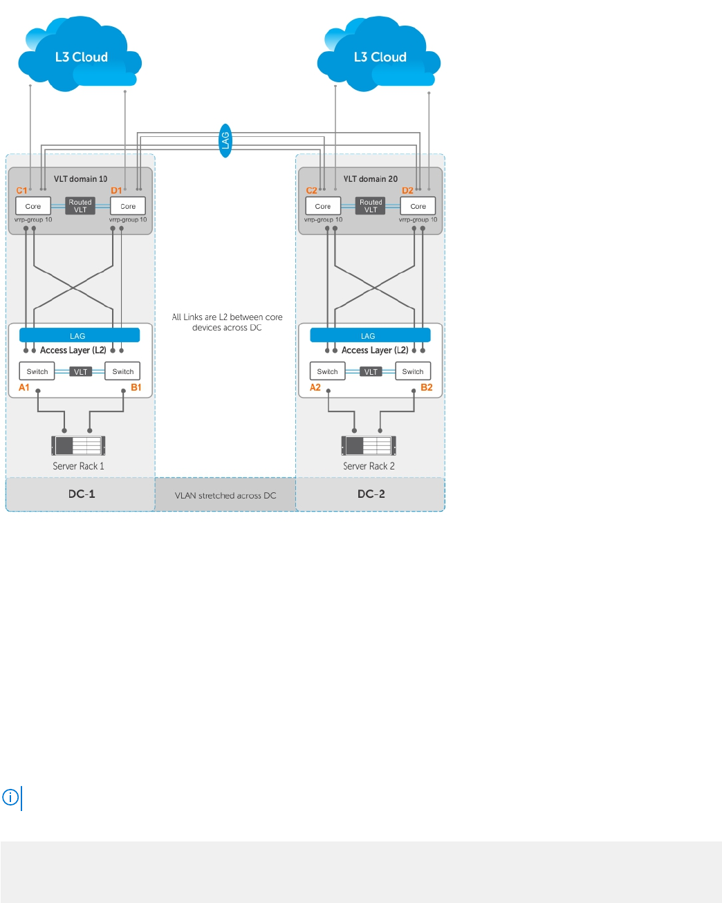
This is achieved by configuring same VRRP group IDs to the extended L3 VLANs and VRRP stays active-active across all four
VLT nodes even though they are in two different VLT domains.
The following illustration shows a sample configuration with two data centers:
● Server racks, Rack 1 and Rack 2, are part of data centers DC1 and DC2, respectively.
● Rack 1 is connected to devices A1 and B1 in a Layer 2 network segment.
● Rack 2 is connected to devices A2 and B2 in a Layer 2 network segment.
● A VLT link aggregation group (LAG) is present between A1 and B1 as well as A2 and B2.
● A1 and B1 are connected to core routers, C1 and D1 with VLT routing enabled.
●
A2 and B2 are connected to core routers, C2 and D2, with VLT routing enabled.
● The core routers C1 and D1 in the local VLT domain are connected to the core routers C2 and D2 in the remote VLT Domain
using VLT links.
● The core routers C1 and D1 in local VLT Domain along with C2 and D2 in the remote VLT Domain are part of a Layer 3 cloud.
● The core routers C1, D1, C2, D2 are in a VRRP group with the same vrrp-group ID.
When a virtual machine running in Server Rack 1 migrates to Server Rack 2, L3 packets for that VM are routed through the
default gateway.
The following examples show sample configurations of the core routers.
NOTE: The following configuration assumes that all VLT-related settings are already present on the respective devices.
Sample configuration of C1:
vlt domain 10
peer-link port-channel 128
back-up destination 10.16.140.6
system-mac mac-address 00:00:aa:00:00:00
1082
Virtual Router Redundancy Protocol (VRRP)