
Users Guide

vrrp-group 10
priority 100
virtual-address fe80::10
virtual-address 1::10
no shutdown
R2(conf-if-tf-1/1)#end
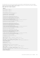
R2#show vrrp
------------------
twentyFiveGigE 1/1, IPv6 VRID: 10, Version: 3, Net:fe80::201:e8ff:fe6a:c59f
VRF: 0 default
State: Master, Priority: 100, Master: fe80::201:e8ff:fe6a:c59f (local)
Hold Down: 0 centisec, Preempt: TRUE, AdvInt: 100 centisec
Accept Mode: FALSE, Master AdvInt: 100 centisec
Adv rcvd: 0, Bad pkts rcvd: 0, Adv sent: 135
Virtual MAC address:
00:00:5e:00:02:0a
Virtual IP address:
1::10 fe80::10
Router 3
R3(conf)#interface twentyFiveGigE 1/2
R3(conf-if-tf-1/2)#no ipv6 address
R3(conf-if-tf-1/2)#ipv6 address 1::2/64
R3(conf-if-tf-1/2)#vrrp-group 10
R2(conf-if-tf-1/2-vrid-10)#virtual-address fe80::10
R2(conf-if-tf-1/2-vrid-10)#virtual-address 1::10
R3(conf-if-tf-1/2-vrid-10)#no shutdown
R3(conf-if-tf-1/2)#show config
interface twentyFiveGigE 1/2
ipv6 address 1::2/64
vrrp-group 10
priority 100
virtual-address fe80::10
virtual-address 1::10
no shutdown
R3(conf-if-tf-1/2)#end
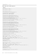
R3#show vrrp
------------------
twentyFiveGigE 1/2, IPv6 VRID: 10, Version: 3, Net:
fe80::201:e8ff:fe6b:1845
VRF: 0 default
State: Backup, Priority: 100, Master: fe80::201:e8ff:fe6a:c59f
Hold Down: 0 centisec, Preempt: TRUE, AdvInt: 100 centisec
Accept Mode: FALSE, Master AdvInt: 100 centisec
Adv rcvd: 11, Bad pkts rcvd: 0, Adv sent: 0
Virtual MAC address:
00:00:5e:00:02:0a
VRRP in a VRF Configuration
The following example shows how to enable VRRP operation in a VRF virtualized network for the following scenarios.
● Multiple VRFs on physical interfaces running VRRP.
● Multiple VRFs on VLAN interfaces running VRRP.
To view a VRRP in a VRF configuration, use the show commands.
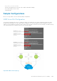
VRRP in a VRF: Non-VLAN Scenario
The following example shows how to enable VRRP in a non-VLAN.
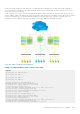
The following example shows a typical use case in which you create three virtualized overlay networks by configuring three
VRFs in two switches. The default gateway to reach the Internet in each VRF is a static route with the next hop being the
virtual IP address configured in VRRP. In this scenario, a single VLAN is associated with each VRF.
Both Switch-1 and Switch-2 have three VRF instances defined: VRF-1, VRF-2, and VRF-3. Each VRF has a separate physical
interface to a LAN switch and an upstream VPN interface to connect to the Internet. Both Switch-1 and Switch-2 use VRRP
1026
Virtual Router Redundancy Protocol (VRRP)