
Administrator Guide
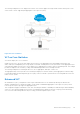
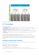


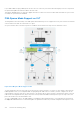


Table Of Contents
- Dell Configuration Guide for the Z9000 System 9.7(0.0)
- Contents
- About this Guide
- Configuration Fundamentals
- Getting Started
- Console Access
- Accessing the CLI Interface and Running Scripts Using SSH
- Default Configuration
- Configuring a Host Name
- Accessing the System Remotely
- Configuring the Enable Password
- Configuration File Management
- Managing the File System
- Enabling Software Features on Devices Using a Command Option
- View Command History
- Upgrading Dell Networking OS
- Using HTTP for File Transfers
- Using Hashes to Validate Software Images
- Management
- Configuring Privilege Levels
- Configuring Logging
- Log Messages in the Internal Buffer
- Disabling System Logging
- Sending System Messages to a Syslog Server
- Changing System Logging Settings
- Display the Logging Buffer and the Logging Configuration
- Configuring a UNIX Logging Facility Level
- Synchronizing Log Messages
- Enabling Timestamp on Syslog Messages
- File Transfer Services
- Terminal Lines
- Setting Time Out of EXEC Privilege Mode
- Using Telnet to get to Another Network Device
- Lock CONFIGURATION Mode
- Recovering from a Forgotten Password on the Z9000 System
- Recovering from a Failed Start on the Z9000 System
- Restoring the Factory Default Settings
- 802.1X
- The Port-Authentication Process
- Configuring 802.1X
- Important Points to Remember
- Enabling 802.1X
- Configuring Request Identity Re-Transmissions
- Forcibly Authorizing or Unauthorizing a Port
- Re-Authenticating a Port
- Configuring Timeouts
- Configuring Dynamic VLAN Assignment with Port Authentication
- Guest and Authentication-Fail VLANs
- Access Control Lists (ACLs)
- IP Access Control Lists (ACLs)
- IP Fragment Handling
- Configure a Standard IP ACL
- Configure an Extended IP ACL
- Configure Layer 2 and Layer 3 ACLs
- Assign an IP ACL to an Interface
- Applying an IP ACL
- Configure Ingress ACLs
- Configure Egress ACLs
- IP Prefix Lists
- ACL Resequencing
- Route Maps
- Important Points to Remember
- Logging of ACL Processes
- Guidelines for Configuring ACL Logging
- Configuring ACL Logging
- Flow-Based Monitoring Support for ACLs
- Enabling Flow-Based Monitoring
- Access Control List (ACL) VLAN Groups and Content Addressable Memory (CAM)
- Bidirectional Forwarding Detection (BFD)
- Border Gateway Protocol IPv4 (BGPv4)
- Autonomous Systems (AS)
- Sessions and Peers
- Route Reflectors
- BGP Attributes
- Multiprotocol BGP
- Implement BGP with Dell Networking OS
- Configuration Information
- BGP Configuration
- Enabling BGP
- Configuring AS4 Number Representations
- Configuring Peer Groups
- Configuring BGP Fast Fall-Over
- Configuring Passive Peering
- Maintaining Existing AS Numbers During an AS Migration
- Allowing an AS Number to Appear in its Own AS Path
- Enabling Graceful Restart
- Enabling Neighbor Graceful Restart
- Filtering on an AS-Path Attribute
- Regular Expressions as Filters
- Redistributing Routes
- Enabling Additional Paths
- Configuring IP Community Lists
- Configuring an IP Extended Community List
- Filtering Routes with Community Lists
- Manipulating the COMMUNITY Attribute
- Changing MED Attributes
- Changing the LOCAL_PREFERENCE Attribute
- Changing the NEXT_HOP Attribute
- Changing the WEIGHT Attribute
- Enabling Multipath
- Filtering BGP Routes
- Filtering BGP Routes Using Route Maps
- Filtering BGP Routes Using AS-PATH Information
- Configuring BGP Route Reflectors
- Aggregating Routes
- Configuring BGP Confederations
- Enabling Route Flap Dampening
- Changing BGP Timers
- Enabling BGP Neighbor Soft-Reconfiguration
- Route Map Continue
- Enabling MBGP Configurations
- BGP Regular Expression Optimization
- Debugging BGP
- Sample Configurations
- Content Addressable Memory (CAM)
- Control Plane Policing (CoPP)
- Dynamic Host Configuration Protocol (DHCP)
- DHCP Packet Format and Options
- Assign an IP Address using DHCP
- Implementation Information
- Configure the System to be a DHCP Server
- Configure the System to be a Relay Agent
- Configure the System to be a DHCP Client
- Configure the System for User Port Stacking (Option 230)
- Configure Secure DHCP
- Option 82
- DHCP Snooping
- Enabling DHCP Snooping
- Enabling IPv6 DHCP Snooping
- Adding a Static Entry in the Binding Table
- Adding a Static IPV6 DHCP Snooping Binding Table
- Clearing the Binding Table
- Clearing the DHCP IPv6 Binding Table
- Displaying the Contents of the Binding Table
- Displaying the Contents of the DHCPv6 Binding Table
- Debugging the IPv6 DHCP
- IPv6 DHCP Snooping MAC-Address Verification
- Drop DHCP Packets on Snooped VLANs Only
- Dynamic ARP Inspection
- Configuring Dynamic ARP Inspection
- Source Address Validation
- Equal Cost Multi-Path (ECMP)
- Enabling FIPS Cryptography
- Force10 Resilient Ring Protocol (FRRP)
- GARP VLAN Registration Protocol (GVRP)
- Internet Group Management Protocol (IGMP)
- IGMP Protocol Overview
- Configure IGMP
- Viewing IGMP Enabled Interfaces
- Selecting an IGMP Version
- Viewing IGMP Groups
- Adjusting Timers
- Configuring a Static IGMP Group
- Enabling IGMP Immediate-Leave
- IGMP Snooping
- Fast Convergence after MSTP Topology Changes
- Egress Interface Selection (EIS) for HTTP and IGMP Applications
- Designating a Multicast Router Interface
- Interfaces
- Interface Types
- View Basic Interface Information
- Enabling a Physical Interface
- Physical Interfaces
- Egress Interface Selection (EIS)
- Management Interfaces
- VLAN Interfaces
- Loopback Interfaces
- Null Interfaces
- Port Channel Interfaces
- Port Channel Definition and Standards
- Port Channel Benefits
- Port Channel Implementation
- 10/100/1000 Mbps Interfaces in Port Channels
- Configuration Tasks for Port Channel Interfaces
- Creating a Port Channel
- Adding a Physical Interface to a Port Channel
- Reassigning an Interface to a New Port Channel
- Configuring the Minimum Oper Up Links in a Port Channel
- _
- Assigning an IP Address to a Port Channel
- Deleting or Disabling a Port Channel
- Load Balancing Through Port Channels
- Load-Balancing Method
- Changing the Hash Algorithm
- Bulk Configuration
- Defining Interface Range Macros
- Monitoring and Maintaining Interfaces
- Splitting QSFP Ports to SFP+ Ports
- Converting a QSFP or QSFP+ Port to an SFP or SFP+ Port
- Link Dampening
- Link Bundle Monitoring
- Using Ethernet Pause Frames for Flow Control
- Configure the MTU Size on an Interface
- Port-Pipes
- Auto-Negotiation on Ethernet Interfaces
- View Advanced Interface Information
- Dynamic Counters
- Enhanced Validation of Interface Ranges
- Internet Protocol Security (IPSec)
- IPv4 Routing
- IP Addresses
- Configuration Tasks for IP Addresses
- Assigning IP Addresses to an Interface
- Configuring Static Routes
- Configure Static Routes for the Management Interface
- IPv4 Path MTU Discovery Overview
- Using the Configured Source IP Address in ICMP Messages
- Configuring the Duration to Establish a TCP Connection
- Enabling Directed Broadcast
- Resolution of Host Names
- Enabling Dynamic Resolution of Host Names
- Specifying the Local System Domain and a List of Domains
- Configuring DNS with Traceroute
- ARP
- Configuration Tasks for ARP
- Configuring Static ARP Entries
- Enabling Proxy ARP
- Clearing ARP Cache
- ARP Learning via Gratuitous ARP
- Enabling ARP Learning via Gratuitous ARP
- ARP Learning via ARP Request
- Configuring ARP Retries
- ICMP
- Configuration Tasks for ICMP
- Enabling ICMP Unreachable Messages
- UDP Helper
- Enabling UDP Helper
- Configuring a Broadcast Address
- Configurations Using UDP Helper
- UDP Helper with Broadcast-All Addresses
- UDP Helper with Subnet Broadcast Addresses
- UDP Helper with Configured Broadcast Addresses
- UDP Helper with No Configured Broadcast Addresses
- Troubleshooting UDP Helper
- IPv6 Routing
- Protocol Overview
- Implementing IPv6 with Dell Networking OS
- ICMPv6
- Path MTU Discovery
- IPv6 Neighbor Discovery
- Configuration Task List for IPv6 RDNSS
- Secure Shell (SSH) Over an IPv6 Transport
- Configuration Tasks for IPv6
- Configuring IPv6 RA Guard
- Intermediate System to Intermediate System
- IS-IS Protocol Overview
- IS-IS Addressing
- Multi-Topology IS-IS
- Graceful Restart
- Implementation Information
- Configuration Information
- IS-IS Metric Styles
- Configure Metric Values
- Sample Configurations
- Link Aggregation Control Protocol (LACP)
- Introduction to Dynamic LAGs and LACP
- LACP Configuration Tasks
- Shared LAG State Tracking
- LACP Basic Configuration Example
- Setting Up a Threshold for Utilization of High-Gigabit Port Channels
- Enabling the Verification of Member Links Utilization in a High-Gigabit Port Channel
- Viewing Buffer Utilization and Queue Statistics on High-Gigabit Ethernet Backplane Ports
- Layer 2
- Link Layer Discovery Protocol (LLDP)
- 802.1AB (LLDP) Overview
- Optional TLVs
- TIA-1057 (LLDP-MED) Overview
- Configure LLDP
- CONFIGURATION versus INTERFACE Configurations
- Enabling LLDP
- Enabling LLDP on Management Ports
- Advertising TLVs
- Viewing the LLDP Configuration
- Viewing Information Advertised by Adjacent LLDP Agents
- Configuring LLDPDU Intervals
- Configuring Transmit and Receive Mode
- Configuring a Time to Live
- Debugging LLDP
- Relevant Management Objects
- Microsoft Network Load Balancing
- Multicast Source Discovery Protocol (MSDP)
- Anycast RP
- Implementation Information
- Configure Multicast Source Discovery Protocol
- Enable MSDP
- Manage the Source-Active Cache
- Accept Source-Active Messages that Fail the RFP Check
- Specifying Source-Active Messages
- Limiting the Source-Active Messages from a Peer
- Preventing MSDP from Caching a Local Source
- Preventing MSDP from Caching a Remote Source
- Preventing MSDP from Advertising a Local Source
- Logging Changes in Peership States
- Terminating a Peership
- Clearing Peer Statistics
- Debugging MSDP
- MSDP with Anycast RP
- Configuring Anycast RP
- MSDP Sample Configurations
- Multiple Spanning Tree Protocol (MSTP)
- Spanning Tree Variations
- Configure Multiple Spanning Tree Protocol
- Enable Multiple Spanning Tree Globally
- Adding and Removing Interfaces
- Creating Multiple Spanning Tree Instances
- Influencing MSTP Root Selection
- Interoperate with Non-Dell Networking OS Bridges
- Changing the Region Name or Revision
- Modifying Global Parameters
- Modifying the Interface Parameters
- Configuring an EdgePort
- Flush MAC Addresses after a Topology Change
- MSTP Sample Configurations
- Debugging and Verifying MSTP Configurations
- Multicast Features
- Object Tracking
- Open Shortest Path First (OSPFv2 and OSPFv3)
- Protocol Overview
- OSPF with Dell Networking OS
- Configuration Information
- Configuration Task List for OSPFv2 (OSPF for IPv4)
- Enabling OSPFv2
- Assigning a Router ID
- Enabling Multi-Process OSPF (OSPFv2, IPv4 Only)
- Assigning an OSPFv2 Area
- Enable OSPFv2 on Interfaces
- Configuring Stub Areas
- Enabling Passive Interfaces
- Enabling Fast-Convergence
- Changing OSPFv2 Parameters on Interfaces
- Enabling OSPFv2 Authentication
- Enabling OSPFv2 Graceful Restart
- Creating Filter Routes
- Applying Prefix Lists
- Redistributing Routes
- Troubleshooting OSPFv2
- Configuration Task List for OSPFv2 (OSPF for IPv4)
- Sample Configurations for OSPFv2
- Configuration Task List for OSPFv3 (OSPF for IPv6)
- Enabling IPv6 Unicast Routing
- Assigning IPv6 Addresses on an Interface
- Assigning Area ID on an Interface
- Assigning OSPFv3 Process ID and Router ID Globally
- Configuring Stub Areas
- Configuring Passive-Interface
- Redistributing Routes
- Configuring a Default Route
- Enabling OSPFv3 Graceful Restart
- OSPFv3 Authentication Using IPsec
- Troubleshooting OSPFv3
- Policy-based Routing (PBR)
- PIM Sparse-Mode (PIM-SM)
- PIM Source-Specific Mode (PIM-SSM)
- Port Monitoring
- Private VLANs (PVLAN)
- Per-VLAN Spanning Tree Plus (PVST+)
- Protocol Overview
- Implementation Information
- Configure Per-VLAN Spanning Tree Plus
- Enabling PVST+
- Disabling PVST+
- Influencing PVST+ Root Selection
- Modifying Global PVST+ Parameters
- Modifying Interface PVST+ Parameters
- Configuring an EdgePort
- PVST+ in Multi-Vendor Networks
- Enabling PVST+ Extend System ID
- PVST+ Sample Configurations
- Quality of Service (QoS)
- Implementation Information
- Port-Based QoS Configurations
- Policy-Based QoS Configurations
- Enabling QoS Rate Adjustment
- Enabling Strict-Priority Queueing
- Weighted Random Early Detection
- Pre-Calculating Available QoS CAM Space
- Configuring Weights and ECN for WRED
- Configuring WRED and ECN Attributes
- Guidelines for Configuring ECN for Classifying and Color-Marking Packets
- Applying Layer 2 Match Criteria on a Layer 3 Interface
- Applying DSCP and VLAN Match Criteria on a Service Queue
- Routing Information Protocol (RIP)
- Remote Monitoring (RMON)
- Rapid Spanning Tree Protocol (RSTP)
- Protocol Overview
- Configuring Rapid Spanning Tree
- Important Points to Remember
- Configuring Interfaces for Layer 2 Mode
- Enabling Rapid Spanning Tree Protocol Globally
- Adding and Removing Interfaces
- Modifying Global Parameters
- Modifying Interface Parameters
- Enabling SNMP Traps for Root Elections and Topology Changes
- Influencing RSTP Root Selection
- Configuring an EdgePort
- Configuring Fast Hellos for Link State Detection
- Software-Defined Networking (SDN)
- Security
- AAA Accounting
- AAA Authentication
- Obscuring Passwords and Keys
- AAA Authorization
- RADIUS
- TACACS+
- Protection from TCP Tiny and Overlapping Fragment Attacks
- Enabling SCP and SSH
- Using SCP with SSH to Copy a Software Image
- Removing the RSA Host Keys and Zeroizing Storage
- Configuring When to Re-generate an SSH Key
- Configuring the SSH Server Key Exchange Algorithm
- Configuring the HMAC Algorithm for the SSH Server
- Configuring the SSH Server Cipher List
- Secure Shell Authentication
- Troubleshooting SSH
- Telnet
- VTY Line and Access-Class Configuration
- Role-Based Access Control
- Service Provider Bridging
- sFlow
- Simple Network Management Protocol (SNMP)
- Protocol Overview
- Implementation Information
- SNMPv3 Compliance With FIPS
- Configuration Task List for SNMP
- Important Points to Remember
- Set up SNMP
- Reading Managed Object Values
- Writing Managed Object Values
- Configuring Contact and Location Information using SNMP
- Subscribing to Managed Object Value Updates using SNMP
- Enabling a Subset of SNMP Traps
- Copy Configuration Files Using SNMP
- Copying a Configuration File
- Copying Configuration Files via SNMP
- Copying the Startup-Config Files to the Running-Config
- Copying the Startup-Config Files to the Server via FTP
- Copying the Startup-Config Files to the Server via TFTP
- Copy a Binary File to the Startup-Configuration
- Additional MIB Objects to View Copy Statistics
- Obtaining a Value for MIB Objects
- MIB Support to Display the Available Memory Size on Flash
- MIB Support to Display the Software Core Files Generated by the System
- Manage VLANs using SNMP
- Managing Overload on Startup
- Enabling and Disabling a Port using SNMP
- Fetch Dynamic MAC Entries using SNMP
- Deriving Interface Indices
- Monitor Port-Channels
- Troubleshooting SNMP Operation
- Storm Control
- Spanning Tree Protocol (STP)
- Protocol Overview
- Configure Spanning Tree
- Important Points to Remember
- Configuring Interfaces for Layer 2 Mode
- Enabling Spanning Tree Protocol Globally
- Adding an Interface to the Spanning Tree Group
- Modifying Global Parameters
- Modifying Interface STP Parameters
- Enabling PortFast
- Selecting STP Root
- STP Root Guard
- Enabling SNMP Traps for Root Elections and Topology Changes
- Configuring Spanning Trees as Hitless
- STP Loop Guard
- Displaying STP Guard Configuration
- System Time and Date
- Tunneling
- Configuring a Tunnel
- Configuring Tunnel Keepalive Settings
- Configuring a Tunnel Interface
- Configuring Tunnel allow-remote Decapsulation
- Configuring Tunnel source anylocal Decapsulation
- Guidelines for Configuring Multipoint Receive-Only Tunnels
- Multipoint Receive-Only Type and IP Unnumbered Interfaces for Tunnels
- Upgrade Procedures
- Virtual LANs (VLANs)
- Virtual Link Trunking (VLT)
- Overview
- VLT Terminology
- Configure Virtual Link Trunking
- RSTP Configuration
- Preventing Forwarding Loops in a VLT Domain
- Sample RSTP Configuration
- Configuring VLT
- Configuring a VLT Interconnect
- Enabling VLT and Creating a VLT Domain
- Configuring a VLT Backup Link
- Configuring a VLT Port Delay Period
- Reconfiguring the Default VLT Settings (Optional)
- Connecting a VLT Domain to an Attached Access Device (Switch or Server)
- Configuring a VLT VLAN Peer-Down (Optional)
- Configuring Enhanced VLT (eVLT) (Optional)
- VLT Sample Configuration
- PVST+ Configuration
- eVLT Configuration Example
- PIM-Sparse Mode Configuration Example
- Verifying a VLT Configuration
- Additional VLT Sample Configurations
- Troubleshooting VLT
- Reconfiguring Stacked Switches as VLT
- Specifying VLT Nodes in a PVLAN
- Configuring a VLT VLAN or LAG in a PVLAN
- Proxy ARP Capability on VLT Peer Nodes
- VLT Nodes as Rendezvous Points for Multicast Resiliency
- Configuring VLAN-Stack over VLT
- VLT Proxy Gateway
- Virtual Router Redundancy Protocol (VRRP)
- VRRP Overview
- VRRP Benefits
- VRRP Implementation
- VRRP Configuration
- Configuration Task List
- Creating a Virtual Router
- Configuring the VRRP Version for an IPv4 Group
- Assign Virtual IP addresses
- Configuring a Virtual IP Address
- Setting VRRP Group (Virtual Router) Priority
- Configuring VRRP Authentication
- Disabling Preempt
- Changing the Advertisement Interval
- Track an Interface or Object
- Tracking an Interface
- Setting VRRP Initialization Delay
- Configuration Task List
- Sample Configurations
- Z-Series Debugging and Diagnostics
- Standards Compliance
○ In a VLT domain, VRRP interoperates with virtual link trunks that carry traffic to and from access devices (refer to
Overview). The VLT peers belong to the same VRRP group and are assigned master and backup roles. Each peer actively
forwards L3 traffic, reducing the traffic flow over the VLT interconnect.
○ VRRP elects the router with the highest priority as the master in the VRRP group. To ensure VRRP operation in a VLT
domain, configure VRRP group priority on each VLT peer so that a peer is either the master or backup for all VRRP
groups configured on its interfaces. For more information, refer to Setting VRRP Group (Virtual Router) Priority.
○ To verify that a VLT peer is consistently configured for either the master or backup role in all VRRP groups, use the
show vrrp command on each peer.
○ Also configure the same L3 routing (static and dynamic) on each peer so that the L3 reachability and routing tables are
identical on both VLT peers. Both the VRRP master and backup peers must be able to locally forward L3 traffic in the
same way.
○ In a VLT domain, although both VLT peers actively participate in L3 forwarding as the VRRP master or backup router, the
show vrrp command output displays one peer as master and the other peer as backup.
● Failure scenarios
○ On a link failover, when a VLT port channel fails, the traffic destined for that VLT port channel is redirected to the VLTi
to avoid flooding.
○ When a VLT switch determines that a VLT port channel has failed (and that no other local port channels are available),
the peer with the failed port channel notifies the remote peer that it no longer has an active port channel for a link. The
remote peer then enables data forwarding across the interconnect trunk for packets that would otherwise have been
forwarded over the failed port channel. This mechanism ensures reachability and provides loop management. If the VLT
interconnect fails, the VLT software on the primary switch checks the status of the remote peer using the backup link. If
the remote peer is up, the secondary switch disables all VLT ports on its device to prevent loops.
○ If all ports in the VLT interconnect fail, or if the messaging infrastructure fails to communicate across the interconnect
trunk, the VLT management system uses the backup link interface to determine whether the failure is a link-level failure
or whether the remote peer has failed entirely. If the remote peer is still alive (heartbeat messages are still being
received), the VLT secondary switch disables its VLT port channels. If keepalive messages from the peer are not being
received, the peer continues to forward traffic, assuming that it is the last device available in the network. In either case,
after recovery of the peer link or reestablishment of message forwarding across the interconnect trunk, the two VLT
peers resynchronize any MAC addresses learned while communication was interrupted and the VLT system continues
normal data forwarding.
○ If the primary chassis fails, the secondary chassis takes on the operational role of the primary.
● The SNMP MIB reports VLT statistics.
Primary and Secondary VLT Peers
To prevent issues when connectivity between peers is lost, you can designate Primary and Secondary roles for VLT peers . You
can elect or configure the Primary Peer. By default, the peer with the lowest MAC address is selected as the Primary Peer. You
can configure another peer as the Primary Peer using the VLT domain domain-id role priority priority-value
command.
If the VLTi link fails, the status of the remote VLT Primary Peer is checked using the backup link. If the remote VLT Primary
Peer is available, the Secondary Peer disables all VLT ports to prevent loops.
If all ports in the VLTi link fail or if the communication between VLTi links fails, VLT checks the backup link to determine the
cause of the failure. If the failed peer can still transmit heartbeat messages, the Secondary Peer disables all VLT member ports
and any Layer 3 interfaces attached to the VLAN associated with the VLT domain. If heartbeat messages are not received, the
Secondary Peer forwards traffic assumes the role of the Primary Peer. If the original Primary Peer is restored, the VLT peer
reassigned as the Primary Peer retains this role and the other peer must be reassigned as a Secondary Peer. Peer role changes
are reported as SNMP traps.
RSTP and VLT
VLT provides loop-free redundant topologies and does not require RSTP.
RSTP can cause temporary port state blocking and may cause topology changes after link or node failures. Spanning tree
topology changes are distributed to the entire layer 2 network, which can cause a network-wide flush of learned MAC and
ARP addresses, requiring these addresses to be re-learned. However, enabling RSTP can detect potential loops caused by
non-system issues such as cabling errors or incorrect configurations. To minimize possible topology changes after link or node
failure, RSTP is useful for potential loop detection. Configure RSTP using the following specifications.
The following recommendations help you avoid these issues and the associated traffic loss caused by using RSTP when you
enable VLT on both VLT peers:
716
Virtual Link Trunking (VLT)