
Administrator Guide

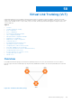
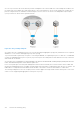
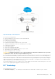
Table Of Contents
- Dell Configuration Guide for the S6000 System 9.14.2.5
- About this Guide
- Configuration Fundamentals
- Getting Started
- Management
- Configuring Privilege Levels
- Configuring Logging
- Log Messages in the Internal Buffer
- Disabling System Logging
- Sending System Messages to a Syslog Server
- Track Login Activity
- Limit Concurrent Login Sessions
- Enabling Secured CLI Mode
- Changing System Logging Settings
- Display the Logging Buffer and the Logging Configuration
- Configuring a UNIX Logging Facility Level
- Synchronizing Log Messages
- Enabling Timestamp on Syslog Messages
- File Transfer Services
- Terminal Lines
- Setting Timeout for EXEC Privilege Mode
- Using Telnet to get to Another Network Device
- Lock CONFIGURATION Mode
- Recovering from a Forgotten Password on the S6000
- Recovering from a Forgotten Enable Password
- Recovering from a Failed Start on the S6000
- Restoring the Factory Default Settings
- Viewing the Reason for Last System Reboot
- Disabling Syslog Messages for SNMP Authentication Failure Events
- 802.1X
- Port-Authentication Process
- Configuring 802.1X
- Important Points to Remember
- Enabling 802.1X
- Configuring dot1x Profile
- Configuring MAC addresses for a do1x Profile
- Configuring the Static MAB and MAB Profile
- Configuring Critical VLAN
- Configuring Request Identity Re-Transmissions
- Forcibly Authorizing or Unauthorizing a Port
- Re-Authenticating a Port
- Configuring Timeouts
- Configuring Dynamic VLAN Assignment with Port Authentication
- Guest and Authentication-Fail VLANs
- Access Control List (ACL) VLAN Groups and Content Addressable Memory (CAM)
- Access Control Lists (ACLs)
- IP Access Control Lists (ACLs)
- Important Points to Remember
- IP Fragment Handling
- Configure a Standard IP ACL
- Configure an Extended IP ACL
- Configure Layer 2 and Layer 3 ACLs
- Assign an IP ACL to an Interface
- Applying an IP ACL
- Configure Ingress ACLs
- Configure Egress ACLs
- IP Prefix Lists
- ACL Remarks
- ACL Resequencing
- Route Maps
- Configuring UDF ACL
- Configuring IP Mirror Access Group
- Bidirectional Forwarding Detection (BFD)
- Border Gateway Protocol (BGP)
- BGP IP version 4 (BGPv4) Overview
- Basic BGP configuration tasks
- Advanced BGP configuration tasks
- Route-refresh and Soft-reconfiguration
- Aggregating Routes
- Filtering BGP
- Configuring BGP Fast Fall-Over
- Configuring Passive Peering
- Enabling Graceful Restart
- Redistributing Routes
- Enabling Additional Paths
- Configuring IP Community Lists
- Configuring an IP Extended Community List
- Configure BGP attributes
- Enabling Multipath
- Route Reflectors
- Enabling Route Flap Dampening
- Changing BGP keepalive and hold timers
- Setting the extended timer
- Enabling or disabling BGP neighbors
- Route Map Continue
- Configuring BGP Confederations
- Configuring a BGP VRF address family
- Maintaining Existing AS Numbers During an AS Migration
- Allowing an AS Number to Appear in its Own AS Path
- Enabling MBGP Configurations
- MBGP support for IPv6
- Configuring IPv6 MBGP between peers
- Example-Configuring IPv4 and IPv6 neighbors
- Configure IPv6 NH Automatically for IPv6 Prefix Advertised over IPv4 Neighbor
- BGP Regular Expression Optimization
- Debugging BGP
- Content Addressable Memory (CAM)
- Control Plane Policing (CoPP)
- Data Center Bridging (DCB)
- Ethernet Enhancements in Data Center Bridging
- Enabling Data Center Bridging
- Data Center Bridging: Default Configuration
- Configuring Priority-Based Flow Control
- Configuring Lossless Queues
- Configuring PFC in a DCB Map
- Configuring PFC without a DCB Map
- Behavior of Tagged Packets
- Configuration Example for DSCP and PFC Priorities
- SNMP Support for PFC and Buffer Statistics Tracking
- Performing PFC Using DSCP Bits Instead of 802.1p Bits
- PFC and ETS Configuration Examples
- Using PFC to Manage Converged Ethernet Traffic
- Operations on Untagged Packets
- Generation of PFC for a Priority for Untagged Packets
- Configure Enhanced Transmission Selection
- Hierarchical Scheduling in ETS Output Policies
- Using ETS to Manage Converged Ethernet Traffic
- Applying DCB Policies in a Switch Stack
- Configure a DCBx Operation
- Verifying the DCB Configuration
- QoS dot1p Traffic Classification and Queue Assignment
- Configuring the Dynamic Buffer Method
- Sample DCB Configuration
- Dynamic Host Configuration Protocol (DHCP)
- DHCP Packet Format and Options
- Assign an IP Address using DHCP
- Implementation Information
- Configure the System to be a DHCP Server
- Configure the System to be a DHCP Client
- DHCP Relay When DHCP Server and Client are in Different VRFs
- Non-default VRF configuration for DHCPv6 helper address
- Configuring DHCP relay source interface
- Configure the System for User Port Stacking (Option 230)
- Configure Secure DHCP
- Option 82 (DHCPv4 relay options)
- DHCPv6 relay agent options
- DHCP Snooping
- Enabling DHCP Snooping
- Enabling IPv6 DHCP Snooping
- Adding a Static Entry in the Binding Table
- Adding a Static IPV6 DHCP Snooping Binding Table
- Clearing the Binding Table
- Clearing the DHCP IPv6 Binding Table
- Displaying the Contents of the Binding Table
- Displaying the Contents of the DHCPv6 Binding Table
- Debugging the IPv6 DHCP
- IPv6 DHCP Snooping MAC-Address Verification
- Configuring the DHCP secondary-subnet
- Drop DHCP Packets on Snooped VLANs Only
- Dynamic ARP Inspection
- Configuring Dynamic ARP Inspection
- Source Address Validation
- Equal Cost Multi-Path (ECMP)
- FIP Snooping
- Fibre Channel over Ethernet
- Ensure Robustness in a Converged Ethernet Network
- FIP Snooping on Ethernet Bridges
- FIP Snooping in a Switch Stack
- Using FIP Snooping
- FIP Snooping Prerequisites
- Important Points to Remember
- Enabling the FCoE Transit Feature
- Enable FIP Snooping on VLANs
- Configure the FC-MAP Value
- Configure a Port for a Bridge-to-Bridge Link
- Configure a Port for a Bridge-to-FCF Link
- Impact on Other Software Features
- FIP Snooping Restrictions
- Configuring FIP Snooping
- Displaying FIP Snooping Information
- FCoE Transit Configuration Example
- Flex Hash and Optimized Boot-Up
- Force10 Resilient Ring Protocol (FRRP)
- GARP VLAN Registration Protocol (GVRP)
- Internet Group Management Protocol (IGMP)
- IGMP Protocol Overview
- Configure IGMP
- Viewing IGMP Enabled Interfaces
- Selecting an IGMP Version
- Viewing IGMP Groups
- Viewing IGMP Snooping Groups
- Adjusting Timers
- Enabling IGMP Immediate-Leave
- IGMP Snooping
- Fast Convergence after MSTP Topology Changes
- Egress Interface Selection (EIS) for HTTP and IGMP Applications
- Designating a Multicast Router Interface
- Interfaces
- Interface Types
- View Basic Interface Information
- Resetting an Interface to its Factory Default State
- Enabling a Physical Interface
- Physical Interfaces
- Automatic recovery of an Err-disabled interface
- Egress Interface Selection (EIS)
- Management Interfaces
- VLAN Interfaces
- Loopback Interfaces
- Null Interfaces
- Configuring Port Delay
- Port Channel Interfaces
- Port Channel Definition and Standards
- Port Channel Benefits
- Port Channel Implementation
- Interfaces in Port Channels
- Configuration Tasks for Port Channel Interfaces
- Creating a Port Channel
- Adding a Physical Interface to a Port Channel
- Reassigning an Interface to a New Port Channel
- Configuring the Minimum Oper Up Links in a Port Channel
- Adding or Removing a Port Channel from a VLAN
- Assigning an IP Address to a Port Channel
- Deleting or Disabling a Port Channel
- Load Balancing Through Port Channels
- Changing the Hash Algorithm
- Bulk Configuration
- Defining Interface Range Macros
- Monitoring and Maintaining Interfaces
- Non Dell-Qualified Transceivers
- Splitting 40G Ports without Reload
- Splitting QSFP Ports to SFP+ Ports
- Converting a QSFP or QSFP+ Port to an SFP or SFP+ Port
- Configuring wavelength for 10–Gigabit SFP+ optics
- Link Dampening
- Link Bundle Monitoring
- Using Ethernet Pause Frames for Flow Control
- Configure the MTU Size on an Interface
- Port-Pipes
- Auto-Negotiation on Ethernet Interfaces
- View Advanced Interface Information
- Configuring the Traffic Sampling Size Globally
- Dynamic Counters
- Compressing Configuration Files
- IPv4 Routing
- IP Addresses
- Configuration Tasks for IP Addresses
- Assigning IP Addresses to an Interface
- Configuring Static Routes
- Configure Static Routes for the Management Interface
- Using the Configured Source IP Address in ICMP Messages
- Configuring the Duration to Establish a TCP Connection
- Enabling Directed Broadcast
- Resolution of Host Names
- Enabling Dynamic Resolution of Host Names
- Specifying the Local System Domain and a List of Domains
- Configuring DNS with Traceroute
- ARP
- Configuration Tasks for ARP
- Configuring Static ARP Entries
- Enabling Proxy ARP
- Clearing ARP Cache
- ARP Learning via Gratuitous ARP
- Enabling ARP Learning via Gratuitous ARP
- ARP Learning via ARP Request
- Configuring ARP Retries
- ICMP
- Configuration Tasks for ICMP
- Enabling ICMP Unreachable Messages
- ICMP Redirects
- UDP Helper
- Enabling UDP Helper
- Configuring a Broadcast Address
- Configurations Using UDP Helper
- UDP Helper with Broadcast-All Addresses
- UDP Helper with Subnet Broadcast Addresses
- UDP Helper with Configured Broadcast Addresses
- UDP Helper with No Configured Broadcast Addresses
- Troubleshooting UDP Helper
- IPv6 Routing
- Protocol Overview
- Implementing IPv6 with Dell EMC Networking OS
- ICMPv6
- Path MTU discovery
- IPv6 Neighbor Discovery
- Secure Shell (SSH) Over an IPv6 Transport
- Configuration Tasks for IPv6
- Adjusting Your CAM-Profile
- Assigning an IPv6 Address to an Interface
- Assigning a Static IPv6 Route
- Configuring Telnet with IPv6
- SNMP over IPv6
- Displaying IPv6 Information
- Displaying an IPv6 Interface Information
- Showing IPv6 Routes
- Showing the Running-Configuration for an Interface
- Clearing IPv6 Routes
- Disabling ND Entry Timeout
- Configuring IPv6 RA Guard
- iSCSI Optimization
- iSCSI Optimization Overview
- Monitoring iSCSI Traffic Flows
- Application of Quality of Service to iSCSI Traffic Flows
- Information Monitored in iSCSI Traffic Flows
- Detection and Auto-Configuration for Dell EqualLogic Arrays
- Configuring Detection and Ports for Dell Compellent Arrays
- Synchronizing iSCSI Sessions Learned on VLT-Lags with VLT-Peer
- Enable and Disable iSCSI Optimization
- Default iSCSI Optimization Values
- iSCSI Optimization Prerequisites
- Configuring iSCSI Optimization
- Displaying iSCSI Optimization Information
- iSCSI Optimization Overview
- Intermediate System to Intermediate System
- IS-IS Protocol Overview
- IS-IS Addressing
- Multi-Topology IS-IS
- Graceful Restart
- Implementation Information
- Configuration Information
- IS-IS Metric Styles
- Configure Metric Values
- Sample Configurations
- In-Service Software Upgrade
- Link Aggregation Control Protocol (LACP)
- Layer 2
- Manage the MAC Address Table
- MAC Learning Limit
- Setting the MAC Learning Limit
- mac learning-limit Dynamic
- mac learning-limit mac-address-sticky
- mac learning-limit station-move
- mac learning-limit no-station-move
- Learning Limit Violation Actions
- Setting Station Move Violation Actions
- Recovering from Learning Limit and Station Move Violations
- Disabling MAC Address Learning on the System
- Enabling port security
- NIC Teaming
- Configure Redundant Pairs
- Far-End Failure Detection
- Link Layer Discovery Protocol (LLDP)
- 802.1AB (LLDP) Overview
- Optional TLVs
- TIA-1057 (LLDP-MED) Overview
- Configure LLDP
- CONFIGURATION versus INTERFACE Configurations
- Enabling LLDP
- Enabling LLDP on Management Ports
- Advertising TLVs
- Storing and Viewing Unrecognized LLDP TLVs
- Viewing the LLDP Configuration
- Viewing Information Advertised by Adjacent LLDP Neighbors
- Configuring LLDPDU Intervals
- Configuring LLDP Notification Interval
- Configuring Transmit and Receive Mode
- Configuring the Time to Live Value
- Debugging LLDP
- Relevant Management Objects
- Microsoft Network Load Balancing
- Multicast Source Discovery Protocol (MSDP)
- Anycast RP
- Implementation Information
- Configure Multicast Source Discovery Protocol
- Enable MSDP
- Manage the Source-Active Cache
- Accept Source-Active Messages that Fail the RFP Check
- Specifying Source-Active Messages
- Limiting the Source-Active Messages from a Peer
- Preventing MSDP from Caching a Local Source
- Preventing MSDP from Caching a Remote Source
- Preventing MSDP from Advertising a Local Source
- Logging Changes in Peership States
- Terminating a Peership
- Clearing Peer Statistics
- Debugging MSDP
- MSDP with Anycast RP
- Configuring Anycast RP
- MSDP Sample Configurations
- Multiple Spanning Tree Protocol (MSTP)
- Spanning Tree Variations
- Configure Multiple Spanning Tree Protocol
- Enable Multiple Spanning Tree Globally
- Adding and Removing Interfaces
- Creating Multiple Spanning Tree Instances
- Influencing MSTP Root Selection
- Interoperate with Non-Dell Bridges
- Changing the Region Name or Revision
- Modifying Global Parameters
- Modifying the Interface Parameters
- Setting STP path cost as constant
- Configuring an EdgePort
- Flush MAC Addresses after a Topology Change
- MSTP Sample Configurations
- Debugging and Verifying MSTP Configurations
- Multicast Features
- Object Tracking
- Open Shortest Path First (OSPFv2 and OSPFv3)
- Protocol Overview
- OSPF with Dell EMC Networking OS
- Configuration Information
- Configuration Task List for OSPFv2 (OSPF for IPv4)
- Enabling OSPFv2
- Assigning a Router ID
- Assigning an OSPFv2 Area
- Enable OSPFv2 on Interfaces
- Configuring Stub Areas
- Enabling Passive Interfaces
- Enabling Fast-Convergence
- Changing OSPFv2 Parameters on Interfaces
- Enabling OSPFv2 Authentication
- Enabling OSPFv2 Graceful Restart
- Creating Filter Routes
- Applying Prefix Lists
- Redistributing Routes
- Troubleshooting OSPFv2
- Sample Configurations for OSPFv2
- Configuration Task List for OSPFv2 (OSPF for IPv4)
- OSPFv3 NSSA
- Configuration Task List for OSPFv3 (OSPF for IPv6)
- Enabling IPv6 Unicast Routing
- Applying cost for OSPFv3
- Assigning IPv6 Addresses on an Interface
- Assigning Area ID on an Interface
- Assigning OSPFv3 Process ID and Router ID Globally
- Assigning OSPFv3 Process ID and Router ID to a VRF
- Configuring Stub Areas
- Configuring Passive-Interface
- Redistributing Routes
- Configuring a Default Route
- Enabling OSPFv3 Graceful Restart
- OSPFv3 Authentication Using IPsec
- Troubleshooting OSPFv3
- MIB Support for OSPFv3
- Policy-based Routing (PBR)
- PIM Sparse-Mode (PIM-SM)
- PIM Source-Specific Mode (PIM-SSM)
- Port Monitoring
- Important Points to Remember
- Port Monitoring
- Configuring Port Monitoring
- Configuring Monitor Multicast Queue
- Flow-Based Monitoring
- Remote Port Mirroring
- Encapsulated Remote Port Monitoring
- ERPM Behavior on a typical Dell EMC Networking OS
- Port Monitoring on VLT
- Per-VLAN Spanning Tree Plus (PVST+)
- Protocol Overview
- Implementation Information
- Configure Per-VLAN Spanning Tree Plus
- Enabling PVST+
- Disabling PVST+
- Influencing PVST+ Root Selection
- Modifying Global PVST+ Parameters
- Modifying Interface PVST+ Parameters
- Configuring an EdgePort
- PVST+ in Multi-Vendor Networks
- Enabling PVST+ Extend System ID
- PVST+ Sample Configurations
- Quality of Service (QoS)
- Implementation Information
- Port-Based QoS Configurations
- Policy-Based QoS Configurations
- Enabling QoS Rate Adjustment
- Enabling Strict-Priority Queueing
- Queue Classification Requirements for PFC Functionality
- Support for marking dot1p value in L3 Input Qos Policy
- Weighted Random Early Detection
- Pre-Calculating Available QoS CAM Space
- Specifying Policy-Based Rate Shaping in Packets Per Second
- Configuring Policy-Based Rate Shaping
- Configuring Weights and ECN for WRED
- Configuring WRED and ECN Attributes
- Guidelines for Configuring ECN for Classifying and Color-Marking Packets
- Applying Layer 2 Match Criteria on a Layer 3 Interface
- Enabling Buffer Statistics Tracking
- Routing Information Protocol (RIP)
- Remote Monitoring (RMON)
- Rapid Spanning Tree Protocol (RSTP)
- Protocol Overview
- Configuring Rapid Spanning Tree
- Important Points to Remember
- Configuring Interfaces for Layer 2 Mode
- Enabling Rapid Spanning Tree Protocol Globally
- Adding and Removing Interfaces
- Modifying Global Parameters
- Modifying Interface Parameters
- Enabling SNMP Traps for Root Elections and Topology Changes
- Influencing RSTP Root Selection
- Configuring an EdgePort
- Configuring Fast Hellos for Link State Detection
- Software-Defined Networking (SDN)
- Security
- AAA Accounting
- AAA Authentication
- Obscuring Passwords and Keys
- AAA Authorization
- RADIUS
- RADIUS Authentication
- Configuration Task List for RADIUS
- Support for Change of Authorization and Disconnect Messages packets
- Change of Authorization (CoA) packets
- Disconnect Messages
- Attributes
- Error-cause Values
- CoA Packet Processing
- CoA or DM Discard
- Disconnect Message Processing
- Configuring DAC
- Configuring the port number
- Configuring shared key
- Disconnecting administrative users logged in through RADIUS
- Configuring CoA to bounce 802.1x enabled ports
- Configuring CoA to re-authenticate 802.1x sessions
- Terminating the 802.1x user session
- Disabling 802.1x enabled port
- Important points to remember
- Configuring replay protection
- Rate-limiting RADIUS packets
- Configuring time-out value
- TACACS+
- Protection from TCP Tiny and Overlapping Fragment Attacks
- Enabling SCP and SSH
- Using SCP with SSH to Copy a Software Image
- Removing the RSA Host Keys and Zeroizing Storage
- Configuring When to Re-generate an SSH Key
- Configuring the SSH Server Key Exchange Algorithm
- Configuring the HMAC Algorithm for the SSH Server
- Configuring the HMAC Algorithm for the SSH Client
- Configuring the SSH Server Cipher List
- Configuring the SSH Client Cipher List
- Configuring DNS in the SSH Server
- Secure Shell Authentication
- Troubleshooting SSH
- Telnet
- VTY Line and Access-Class Configuration
- Role-Based Access Control
- Two Factor Authentication (2FA)
- Configuring the System to Drop Certain ICMP Reply Messages
- SSH Lockout Settings
- Dell EMC Networking OS Security Hardening
- Service Provider Bridging
- sFlow
- Simple Network Management Protocol (SNMP)
- Protocol Overview
- Implementation Information
- SNMPv3 Compliance With FIPS
- Configuration Task List for SNMP
- Important Points to Remember
- Set up SNMP
- Reading Managed Object Values
- Writing Managed Object Values
- Configuring Contact and Location Information using SNMP
- Subscribing to Managed Object Value Updates using SNMP
- Enabling a Subset of SNMP Traps
- Enabling an SNMP Agent to Notify Syslog Server Failure
- Copy Configuration Files Using SNMP
- Copying a Configuration File
- Copying Configuration Files via SNMP
- Copying the Startup-Config Files to the Running-Config
- Copying the Startup-Config Files to the Server via FTP
- Copying the Startup-Config Files to the Server via TFTP
- Copy a Binary File to the Startup-Configuration
- Additional MIB Objects to View Copy Statistics
- Obtaining a Value for MIB Objects
- MIB Support to Display Reason for Last System Reboot
- MIB Support for Power Monitoring
- MIB Support for 25G, 40G, 50G, 100G Optical Transceiver or DAC cable IDPROM user info
- MIB Support to Display the Available Memory Size on Flash
- MIB Support to Display the Software Core Files Generated by the System
- MIB Support for CAM
- MIB Support for PFC Storm Control
- MIB Support for PFC no-drop-priority L2Dlf Drop
- MIB Support for Monitoring the overall buffer usage for lossy and lossless traffic per XPE
- SNMP Support for WRED Green/Yellow/Red Drop Counters
- MIB Support to Display the Available Partitions on Flash
- MIB Support to Display Egress Queue Statistics
- MIB Support to ECMP Group Count
- MIB Support for entAliasMappingTable
- MIB Support to Display the FCS Error Ratio Details
- MIB Support for LAG
- MIB Support to Display Unrecognized LLDP TLVs
- MIB support for Port Security
- MIB support for MAC notification traps
- Configuring SNMP traps for new MAC learning or station–move
- Manage VLANs using SNMP
- Managing Overload on Startup
- Enabling and Disabling a Port using SNMP
- Fetch Dynamic MAC Entries using SNMP
- Example of Deriving the Interface Index Number
- Monitoring BGP sessions via SNMP
- Monitor Port-Channels
- Troubleshooting SNMP Operation
- Transceiver Monitoring
- Configuring SNMP context name
- Stacking
- Storm Control
- Spanning Tree Protocol (STP)
- Protocol Overview
- Configure Spanning Tree
- Important Points to Remember
- Configuring Interfaces for Layer 2 Mode
- Enabling Spanning Tree Protocol Globally
- Adding an Interface to the Spanning Tree Group
- Modifying Global Parameters
- Modifying Interface STP Parameters
- Enabling PortFast
- Selecting STP Root
- STP Root Guard
- Enabling SNMP Traps for Root Elections and Topology Changes
- Configuring Spanning Trees as Hitless
- STP Loop Guard
- Displaying STP Guard Configuration
- SupportAssist
- System Time and Date
- Network Time Protocol
- Protocol Overview
- Configure the Network Time Protocol
- Enabling NTP
- Configuring NTP Broadcasts
- Disabling NTP on an Interface
- Configuring a Source IP Address for NTP Packets
- Configuring NTP Authentication
- Configuring NTP control key password
- Configuring the NTP Step-Threshold
- Configuring a Custom-defined Period for NTP time Synchronization
- Dell EMC Networking OS Time and Date
- Network Time Protocol
- Tunneling
- Uplink Failure Detection (UFD)
- Upgrade Procedures
- Virtual LANs (VLANs)
- Virtual Link Trunking (VLT)
- Overview
- Configure Virtual Link Trunking
- RSTP Configuration
- Preventing Forwarding Loops in a VLT Domain
- Sample RSTP configuration
- Configuring VLT
- Configuring a VLT Interconnect
- Enabling VLT and Creating a VLT Domain
- Configuring a VLT Backup Link
- Configuring a VLT Port Delay Period
- Reconfiguring the Default VLT Settings (Optional)
- Connecting a VLT Domain to an Attached Access Device (Switch or Server)
- Configuring a VLT VLAN Peer-Down (Optional)
- Configuring Enhanced VLT (Optional)
- VLT Sample Configuration
- PVST+ Configuration
- Peer Routing Configuration Example
- eVLT Configuration Example
- PIM-Sparse Mode Configuration Example
- Verifying a VLT Configuration
- Additional VLT Sample Configurations
- Troubleshooting VLT
- Reconfiguring Stacked Switches as VLT
- Specifying VLT Nodes in a PVLAN
- Configuring a VLT VLAN or LAG in a PVLAN
- Proxy ARP Capability on VLT Peer Nodes
- VLT Nodes as Rendezvous Points for Multicast Resiliency
- Configuring VLAN-Stack over VLT
- IPv6 Peer Routing in VLT Domains Overview
- Configure BFD in VLT Domain
- VXLAN on VLT
- VLT Proxy Gateway
- Virtual Extensible LAN (VXLAN)
- Components of VXLAN network
- Functional Overview of VXLAN Gateway
- VXLAN Frame Format
- Limitations on VXLAN
- Configuring and Controlling VXLAN from the NSX Controller GUI
- Configuring and Controling VXLAN from Nuage Controller GUI
- Configuring VxLAN Gateway
- Displaying VXLAN Configurations
- VXLAN Service nodes for BFD
- Static Virtual Extensible LAN (VXLAN)
- Preserving 802.1 p value across VXLAN tunnels
- VXLAN Scenario
- Routing in and out of VXLAN tunnels
- NSX Controller-based VXLAN for VLT
- Virtual Routing and Forwarding (VRF)
- Virtual Router Redundancy Protocol (VRRP)
- VRRP Overview
- VRRP Benefits
- VRRP Implementation
- VRRP Configuration
- Configuration Task List
- Creating a Virtual Router
- Configuring the VRRP Version for an IPv4 Group
- Assign Virtual IP addresses
- Configuring a Virtual IP Address
- Setting VRRP Group (Virtual Router) Priority
- Configuring VRRP Authentication
- Disabling Preempt
- Changing the Advertisement Interval
- Track an Interface or Object
- Tracking an Interface
- Setting VRRP Initialization Delay
- Configuration Task List
- Sample Configurations
- Proxy Gateway with VRRP
- Debugging and Diagnostics
- Standards Compliance
- X.509v3
- Introduction to X.509v3 certificates
- X.509v3 support in
- Information about installing CA certificates
- Information about Creating Certificate Signing Requests (CSR)
- Information about installing trusted certificates
- Transport layer security (TLS)
- Online Certificate Status Protocol (OSCP)
- Verifying certificates
- Event logging
● VLT backup link — The backup link monitors the connectivity between the VLT peer switches. The backup link sends
configurable, periodic keep alive messages between the VLT peer switches.
● VLT interconnect (VLTi) — The link used to synchronize states between the VLT peer switches. Both ends must be on
10G or 40G interfaces.
● VLT domain — This domain includes both the VLT peer devices, VLT interconnect, and all of the port channels in the VLT
connected to the attached devices. It is also associated to the configuration mode that you must use to assign VLT global
parameters.
● VLT peer device — One of a pair of devices that are connected with the special port channel known as the VLT
interconnect (VLTi).
● Enhanced VLT (eVLT) — Combining two VLT domains. eVLT can operate in layer 2 and layer 3 modes. eVLT is also known
as mVLT.
VLT peer switches have independent management planes. A VLT interconnect between the VLT chassis maintains
synchronization of L2/L3 control planes across the two VLT peer switches.
A separate backup link maintains heartbeat messages across an out-of-band (OOB) management network. The backup link
ensures that node failure conditions are correctly detected and are not confused with failures of the VLT interconnect. VLT
ensures that local traffic on a chassis does not traverse the VLTi and takes the shortest path to the destination via directly
attached links.
The following is a summary of VLT and its functions:
● End devices (such as switches, servers, and so on) connected to a VLT domain consider the two VLT peers as a single
logical switch.
● Although VLT does not require spanning tree protocols, Dell EMC Networking recommends enabling RSTP before
configuring VLT to avoid possible loops from forming due to incorrect configuration.
● You can connect two VLT domains to create an eVLT topology.
● You can use eVLT as layer 2.
● Peer routing enables one VLT node to act as the default gateway for its VLT peer within a VLT domain.
● With peer routing, you need not use VRRP.
● You can use routing protocols in a VLT domain or between VLT domains (eVLT).
● VLT Proxy Gateway enables one VLT domain to act as the default gateway for its peer VLT domain in an eVLT topology.
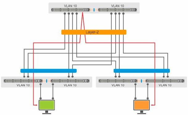
Layer-2 Traffic in VLT Domains
In a VLT domain, the MAC address of any host connected to the VLT peers is synchronized between the VLT nodes. In the
following example, VLAN 10 is spanned across three VLT domains.
Figure 139. Layer-2 Traffic in VLT Domains
If Host 1 from a VLT domain sends a frame to Host 2 in another VLT domain, the frame can use any link shown to reach Host 2.
MAC synchronization between VLT peers handles the traffic flow even if it is hashed and forwarded through the other member
of the port-channel.
948
Virtual Link Trunking (VLT)