
Users Guide
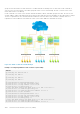

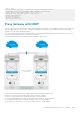
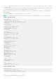

groups on each VRF instance in order that there is one MASTER and one backup router for each VRF. In VRF-1 and VRF-2,
Switch-2 serves as owner-master of the VRRP group and Switch-1 serves as the backup. On VRF-3, Switch-1 is the owner-
master and Switch-2 is the backup.
In VRF-1 and VRF-2 on Switch-2, the virtual IP and node IP address, subnet, and VRRP group are the same. On Switch-1, the
virtual IP address, subnet, and VRRP group are the same in VRF-1 and VRF-2, but the IP address of the node interface is unique.
There is no requirement for the virtual IP and node IP addresses to be the same in VRF-1 and VRF-2; similarly, there is no
requirement for the IP addresses to be different. In VRF-3, the node IP addresses and subnet are unique.
Figure 172. VRRP in a VRF: Non-VLAN Example
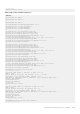
Example of Configuring VRRP in a VRF on Switch-1 (Non-VLAN)
Switch-1
S1(conf)#ip vrf default-vrf 0
!
S1(conf)#ip vrf VRF-1 1
!
S1(conf)#ip vrf VRF-2 2
!
S1(conf)#ip vrf VRF-3 3
!
S1(conf)#interface TenGigabitEthernet 1/1/1
S1(conf-if-te-1/1/1)#ip vrf forwarding VRF-1
S1(conf-if-te-1/1/1)#ip address 10.10.1.5/24
S1(conf-if-te-1/1/1)#vrrp-group 11
% Info: The VRID used by the VRRP group 11 in VRF 1 will be 177.
S1(conf-if-te-1/1/1-vrid-101)#priority 100
S1(conf-if-te-1/1/1-vrid-101)#virtual-address 10.10.1.2
S1(conf-if-te-1/1/1)#no shutdown
!
S1(conf)#interface TenGigabitEthernet 1/2/1
S1(conf-if-te-1/2/1)#ip vrf forwarding VRF-2
S1(conf-if-te-1/2/1)#ip address 10.10.1.6/24
S1(conf-if-te-1/2/1)#vrrp-group 11
% Info: The VRID used by the VRRP group 11 in VRF 2 will be 178.
S1(conf-if-te-1/2/1-vrid-101)#priority 100
S1(conf-if-te-1/2/1-vrid-101)#virtual-address 10.10.1.2
1082
Virtual Router Redundancy Protocol (VRRP)