
White Papers
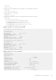
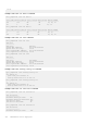
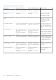
Table Of Contents
- Dell PowerEdge Configuration Guide for the M I/O Aggregator 9.14.1.5
- About this Guide
- Before You Start
- Configuration Fundamentals
- Configuration Cloning
- Data Center Bridging (DCB)
- Ethernet Enhancements in Data Center Bridging
- Enabling Data Center Bridging
- Data Center Bridging: Default Configuration
- Data Center Bridging: Auto-DCB-Enable Mode
- Configuring Priority-Based Flow Control
- Configuring Enhanced Transmission Selection
- Hierarchical Scheduling in ETS Output Policies
- DCBx Operation
- Verifying the DCB Configuration
- QoS dot1p Traffic Classification and Queue Assignment
- Troubleshooting PFC, ETS, and DCBx Operation
- Configuring the Dynamic Buffer Method
- Dynamic Host Configuration Protocol (DHCP)
- FIP Snooping
- Internet Group Management Protocol (IGMP)
- Interfaces
- Interface Auto-Configuration
- Interface Types
- Viewing Interface Information
- Disabling and Re-enabling a Physical Interface
- Layer 2 Mode
- Management Interfaces
- VLAN Membership
- Port Channel Interfaces
- Interface Range
- Monitor and Maintain Interfaces
- Configuring wavelength for 10–Gigabit SFP+ optics
- Flow Control Using Ethernet Pause Frames
- Enabling Pause Frames
- MTU Size
- Setting the Speed and Duplex Mode of Ethernet Interfaces
- Auto-Negotiation on Ethernet Interfaces
- Viewing Interface Information
- Enabling the Management Address TLV on All Interfaces of an Aggregator
- Enhanced Validation of Interface Ranges
- Enhanced Control of Remote Fault Indication Processing
- iSCSI Optimization
- Isolated Networks for Aggregators
- Link Aggregation
- How the LACP is Implemented on an Aggregator
- LACP Example
- Link Aggregation Control Protocol (LACP)
- Configuring Auto LAG
- Configuring the Minimum Number of Links to be Up for Uplink LAGs to be Active
- Optimizing Traffic Disruption Over LAG Interfaces On IOA Switches in VLT Mode
- Preserving LAG and Port Channel Settings in Nonvolatile Storage
- Enabling LACP link-fallback
- Enabling the Verification of Member Links Utilization in a LAG Bundle
- Monitoring the Member Links of a LAG Bundle
- Verifying LACP Operation and LAG Configuration
- Multiple Uplink LAGs
- Multiple Uplink LAGs with 10G Member Ports
- Multiple Uplink LAGs with 40G Member Ports
- Layer 2
- Link Layer Discovery Protocol (LLDP)
- Protocol Data Units
- Configure LLDP
- CONFIGURATION versus INTERFACE Configurations
- Enabling LLDP
- Advertising TLVs
- Optional TLVs
- LLDP Operation
- Storing and Viewing Unrecognized LLDP TLVs
- Viewing the LLDP Configuration
- Viewing Information Advertised by Adjacent LLDP Agents
- Configuring LLDPDU Intervals
- Configuring a Time to Live
- Clearing LLDP Counters
- Debugging LLDP
- Relevant Management Objects
- Object Tracking
- Port Monitoring
- Security
- Understanding Banner Settings
- Accessing the I/O Aggregator Using the CMC Console Only
- AAA Authentication
- AAA Authorization
- RADIUS
- TACACS+
- Enabling SCP and SSH
- Telnet
- VTY Line and Access-Class Configuration
- Dell EMC Networking OS Security Hardening
- Simple Network Management Protocol (SNMP)
- Implementation Information
- Configuring the Simple Network Management Protocol
- Setting Up User-Based Security (SNMPv3)
- Subscribing to Managed Object Value Updates using SNMP
- Enabling a Subset of SNMP Traps
- Reading Managed Object Values
- Displaying the Ports in a VLAN using SNMP
- Fetching Dynamic MAC Entries using SNMP
- Deriving Interface Indices
- MIB Support to Display Reason for Last System Reboot
- MIB Support to Display Egress Queue Statistics
- Monitoring BGP sessions via SNMP
- Monitor Port-Channels
- Entity MIBS
- SNMP Traps for Link Status
- Standard VLAN MIB
- MIB Support to Display the Available Memory Size on Flash
- MIB Support to Display the Software Core Files Generated by the System
- MIB Support to Display the Available Partitions on Flash
- MIB Support to Display Egress Queue Statistics
- MIB Support to Display Egress Queue Statistics
- MIB Support for entAliasMappingTable
- MIB Support for LAG
- MIB Support to Display Unrecognized LLDP TLVs
- Transceiver Monitoring
- Stacking
- Stacking Aggregators
- Stacking Port Numbers
- Stacking in PMUX Mode
- Configuring a Switch Stack
- Configuring the Uplink Speed of Interfaces as 40 Gigabit Ethernet
- Merging Two Operational Stacks
- Verifying a Stack Configuration
- Troubleshooting a Switch Stack
- Upgrading a Switch Stack
- Upgrading a Single Stack Unit
- Storm Control
- Broadcast Storm Control
- SupportAssist
- System Time and Date
- Uplink Failure Detection (UFD)
- Feature Description
- How Uplink Failure Detection Works
- UFD and NIC Teaming
- Important Points to Remember
- Uplink Failure Detection (SMUX mode)
- Configuring Uplink Failure Detection (PMUX mode)
- Clearing a UFD-Disabled Interface (in PMUX mode)
- Displaying Uplink Failure Detection
- Sample Configuration: Uplink Failure Detection
- PMUX Mode of the IO Aggregator
- I/O Aggregator (IOA) Programmable MUX (PMUX) Mode
- Configuring and Changing to PMUX Mode
- Configuring the Commands without a Separate User Account
- Virtual Link Trunking (VLT)
- FC Flex IO Modules
- FC FLEXIO FPORT
- NPIV Proxy Gateway
- Upgrade Procedures
- Debugging and Diagnostics
- Standards Compliance

HeartBeat Messages Received: 978
ICL Hello's Sent: 89
ICL Hello's Received: 89
Additional VLT Sample Configurations
To configure VLT, configure a backup link and interconnect trunk, create a VLT domain, configure a backup link and
interconnect trunk, and connect the peer switches in a VLT domain to an attached access device (switch or server).
Review the following examples of VLT configurations.
Configuring Virtual Link Trunking (VLT Peer 1)
Enable VLT and create a VLT domain with a backup-link and interconnect trunk (VLTi).
Dell_VLTpeer1(conf)#vlt domain 999
Dell_VLTpeer1(conf-vlt-domain)#peer-link port-channel 100
Dell_VLTpeer1(conf-vlt-domain)#back-up destination 10.11.206.35
Dell_VLTpeer1(conf-vlt-domain)#exit
Configure the backup link.
Configure the VLT interconnect (VLTi).
Configure the port channel to an attached device.
Verify that the port channels used in the VLT domain are assigned to the same VLAN.
Configuring Virtual Link Trunking (VLT Peer 2)
Enable VLT and create a VLT domain with a backup-link VLT interconnect (VLTi).
Dell_VLTpeer2(conf)#vlt domain 999
Dell_VLTpeer2(conf-vlt-domain)#peer-link port-channel 100
Dell_VLTpeer2(conf-vlt-domain)#back-up destination 10.11.206.23
Dell_VLTpeer2(conf-vlt-domain)#exit
Configure the backup link.
Configure the VLT interconnect (VLTi).
Configure the port channel to an attached device.
Verify that the port channels used in the VLT domain are assigned to the same VLAN.
Verifying a Port-Channel Connection to a VLT Domain (From an Attached Access Switch)
On an access device, verify the port-channel connection to a VLT domain.
Troubleshooting VLT
To help troubleshoot different VLT issues that may occur, use the following information.
NOTE: For information on VLT Failure mode timing and its impact, contact your Dell Networking representative.
Table 38. Troubleshooting VLT
Description Behavior at Peer Up Behavior During Run Time Action to Take
Bandwidth monitoring A syslog error message and
an SNMP trap is generated
when the VLTi bandwidth
usage goes above the 80%
threshold and when it drops
below 80%.
A syslog error message and an
SNMP trap is generated when
the VLTi bandwidth usage
goes above its threshold.
Depending on the traffic that
is received, the traffic can be
offloaded inVLTi.
Domain ID mismatch
The VLT peer does not boot
up. The VLTi is forced to a
down state.
The VLT peer does not boot
up. The VLTi is forced to a
down state.
Verify the domain ID matches
on both VLT peers.
PMUX Mode of the IO Aggregator 275