
White Papers
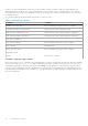
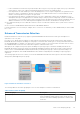
Table Of Contents
- Dell PowerEdge Configuration Guide for the M I/O Aggregator 9.14.1.5
- About this Guide
- Before You Start
- Configuration Fundamentals
- Configuration Cloning
- Data Center Bridging (DCB)
- Ethernet Enhancements in Data Center Bridging
- Enabling Data Center Bridging
- Data Center Bridging: Default Configuration
- Data Center Bridging: Auto-DCB-Enable Mode
- Configuring Priority-Based Flow Control
- Configuring Enhanced Transmission Selection
- Hierarchical Scheduling in ETS Output Policies
- DCBx Operation
- Verifying the DCB Configuration
- QoS dot1p Traffic Classification and Queue Assignment
- Troubleshooting PFC, ETS, and DCBx Operation
- Configuring the Dynamic Buffer Method
- Dynamic Host Configuration Protocol (DHCP)
- FIP Snooping
- Internet Group Management Protocol (IGMP)
- Interfaces
- Interface Auto-Configuration
- Interface Types
- Viewing Interface Information
- Disabling and Re-enabling a Physical Interface
- Layer 2 Mode
- Management Interfaces
- VLAN Membership
- Port Channel Interfaces
- Interface Range
- Monitor and Maintain Interfaces
- Configuring wavelength for 10–Gigabit SFP+ optics
- Flow Control Using Ethernet Pause Frames
- Enabling Pause Frames
- MTU Size
- Setting the Speed and Duplex Mode of Ethernet Interfaces
- Auto-Negotiation on Ethernet Interfaces
- Viewing Interface Information
- Enabling the Management Address TLV on All Interfaces of an Aggregator
- Enhanced Validation of Interface Ranges
- Enhanced Control of Remote Fault Indication Processing
- iSCSI Optimization
- Isolated Networks for Aggregators
- Link Aggregation
- How the LACP is Implemented on an Aggregator
- LACP Example
- Link Aggregation Control Protocol (LACP)
- Configuring Auto LAG
- Configuring the Minimum Number of Links to be Up for Uplink LAGs to be Active
- Optimizing Traffic Disruption Over LAG Interfaces On IOA Switches in VLT Mode
- Preserving LAG and Port Channel Settings in Nonvolatile Storage
- Enabling LACP link-fallback
- Enabling the Verification of Member Links Utilization in a LAG Bundle
- Monitoring the Member Links of a LAG Bundle
- Verifying LACP Operation and LAG Configuration
- Multiple Uplink LAGs
- Multiple Uplink LAGs with 10G Member Ports
- Multiple Uplink LAGs with 40G Member Ports
- Layer 2
- Link Layer Discovery Protocol (LLDP)
- Protocol Data Units
- Configure LLDP
- CONFIGURATION versus INTERFACE Configurations
- Enabling LLDP
- Advertising TLVs
- Optional TLVs
- LLDP Operation
- Storing and Viewing Unrecognized LLDP TLVs
- Viewing the LLDP Configuration
- Viewing Information Advertised by Adjacent LLDP Agents
- Configuring LLDPDU Intervals
- Configuring a Time to Live
- Clearing LLDP Counters
- Debugging LLDP
- Relevant Management Objects
- Object Tracking
- Port Monitoring
- Security
- Understanding Banner Settings
- Accessing the I/O Aggregator Using the CMC Console Only
- AAA Authentication
- AAA Authorization
- RADIUS
- TACACS+
- Enabling SCP and SSH
- Telnet
- VTY Line and Access-Class Configuration
- Dell EMC Networking OS Security Hardening
- Simple Network Management Protocol (SNMP)
- Implementation Information
- Configuring the Simple Network Management Protocol
- Setting Up User-Based Security (SNMPv3)
- Subscribing to Managed Object Value Updates using SNMP
- Enabling a Subset of SNMP Traps
- Reading Managed Object Values
- Displaying the Ports in a VLAN using SNMP
- Fetching Dynamic MAC Entries using SNMP
- Deriving Interface Indices
- MIB Support to Display Reason for Last System Reboot
- MIB Support to Display Egress Queue Statistics
- Monitoring BGP sessions via SNMP
- Monitor Port-Channels
- Entity MIBS
- SNMP Traps for Link Status
- Standard VLAN MIB
- MIB Support to Display the Available Memory Size on Flash
- MIB Support to Display the Software Core Files Generated by the System
- MIB Support to Display the Available Partitions on Flash
- MIB Support to Display Egress Queue Statistics
- MIB Support to Display Egress Queue Statistics
- MIB Support for entAliasMappingTable
- MIB Support for LAG
- MIB Support to Display Unrecognized LLDP TLVs
- Transceiver Monitoring
- Stacking
- Stacking Aggregators
- Stacking Port Numbers
- Stacking in PMUX Mode
- Configuring a Switch Stack
- Configuring the Uplink Speed of Interfaces as 40 Gigabit Ethernet
- Merging Two Operational Stacks
- Verifying a Stack Configuration
- Troubleshooting a Switch Stack
- Upgrading a Switch Stack
- Upgrading a Single Stack Unit
- Storm Control
- Broadcast Storm Control
- SupportAssist
- System Time and Date
- Uplink Failure Detection (UFD)
- Feature Description
- How Uplink Failure Detection Works
- UFD and NIC Teaming
- Important Points to Remember
- Uplink Failure Detection (SMUX mode)
- Configuring Uplink Failure Detection (PMUX mode)
- Clearing a UFD-Disabled Interface (in PMUX mode)
- Displaying Uplink Failure Detection
- Sample Configuration: Uplink Failure Detection
- PMUX Mode of the IO Aggregator
- I/O Aggregator (IOA) Programmable MUX (PMUX) Mode
- Configuring and Changing to PMUX Mode
- Configuring the Commands without a Separate User Account
- Virtual Link Trunking (VLT)
- FC Flex IO Modules
- FC FLEXIO FPORT
- NPIV Proxy Gateway
- Upgrade Procedures
- Debugging and Diagnostics
- Standards Compliance

● Cloning detailed status displays a string that gives detailed description of cloning status. When multiple error or warning
messages are present, the status is separated by the ; delimiter.
● Cloning status codes are useful when there are multiple warning or failure messages. Each warning or failure message is
given a code number; this status can list the message codes that can be decoded when the cloning status string could not
accommodate all the errors and warnings.
● Number of Reboots count the number of reboots required to complete the cloning operation. The reboot details can be
displayed only when the clonability check is done.
Table 2. Cloning Status
Cloning state (captured in command
output)
Cloning status (captured in
command output)
Applicability
Success Cloning file successfully created Source
Success Cloning file compatibility passed Target
Success Target IOA is up and running with
cloning config.
Target
Failure Failed to create running-configuration Source
Failure Failed to extract release information Source
Failure Failed to extract platform information Source
Failure Release version info missing in header Target
Failure Platform info missing in header Target
Failure IOM — mode info missing in header Target
Failure Cloning header missing Target
Failure Release version mismatch Target
Failure Card type mismatch Target
Failure Optional –module mismatch at slot <> Target
Failure IOM-mode mismatch Target
Failure The specified file doesn’t exist to check
compatibility
Target
Failure The specified file cannot be applied as it
‘failed’ compatibility check.
Target
Failure The specified file has not completed for
compatibility check.
Target
Warning Uplink bandwidth mismatch Target
Warning BMP is disabled to complete cloning
operation.
Target
Warning IOM modes are changed from <> to <>
to complete cloning operation.
Target
Warning Minor release version mismatch Target
If the compatibility check passes through, the target aggregator strips the cloning header and proceeds to parsing actual
configuration in the cloning-file. It goes through the configuration one by one and checks if any command or feature requires
Configuration Cloning
31