
White Papers
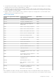
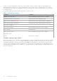
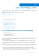
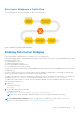
Table Of Contents
- Dell PowerEdge Configuration Guide for the M I/O Aggregator 9.14.1.5
- About this Guide
- Before You Start
- Configuration Fundamentals
- Configuration Cloning
- Data Center Bridging (DCB)
- Ethernet Enhancements in Data Center Bridging
- Enabling Data Center Bridging
- Data Center Bridging: Default Configuration
- Data Center Bridging: Auto-DCB-Enable Mode
- Configuring Priority-Based Flow Control
- Configuring Enhanced Transmission Selection
- Hierarchical Scheduling in ETS Output Policies
- DCBx Operation
- Verifying the DCB Configuration
- QoS dot1p Traffic Classification and Queue Assignment
- Troubleshooting PFC, ETS, and DCBx Operation
- Configuring the Dynamic Buffer Method
- Dynamic Host Configuration Protocol (DHCP)
- FIP Snooping
- Internet Group Management Protocol (IGMP)
- Interfaces
- Interface Auto-Configuration
- Interface Types
- Viewing Interface Information
- Disabling and Re-enabling a Physical Interface
- Layer 2 Mode
- Management Interfaces
- VLAN Membership
- Port Channel Interfaces
- Interface Range
- Monitor and Maintain Interfaces
- Configuring wavelength for 10–Gigabit SFP+ optics
- Flow Control Using Ethernet Pause Frames
- Enabling Pause Frames
- MTU Size
- Setting the Speed and Duplex Mode of Ethernet Interfaces
- Auto-Negotiation on Ethernet Interfaces
- Viewing Interface Information
- Enabling the Management Address TLV on All Interfaces of an Aggregator
- Enhanced Validation of Interface Ranges
- Enhanced Control of Remote Fault Indication Processing
- iSCSI Optimization
- Isolated Networks for Aggregators
- Link Aggregation
- How the LACP is Implemented on an Aggregator
- LACP Example
- Link Aggregation Control Protocol (LACP)
- Configuring Auto LAG
- Configuring the Minimum Number of Links to be Up for Uplink LAGs to be Active
- Optimizing Traffic Disruption Over LAG Interfaces On IOA Switches in VLT Mode
- Preserving LAG and Port Channel Settings in Nonvolatile Storage
- Enabling LACP link-fallback
- Enabling the Verification of Member Links Utilization in a LAG Bundle
- Monitoring the Member Links of a LAG Bundle
- Verifying LACP Operation and LAG Configuration
- Multiple Uplink LAGs
- Multiple Uplink LAGs with 10G Member Ports
- Multiple Uplink LAGs with 40G Member Ports
- Layer 2
- Link Layer Discovery Protocol (LLDP)
- Protocol Data Units
- Configure LLDP
- CONFIGURATION versus INTERFACE Configurations
- Enabling LLDP
- Advertising TLVs
- Optional TLVs
- LLDP Operation
- Storing and Viewing Unrecognized LLDP TLVs
- Viewing the LLDP Configuration
- Viewing Information Advertised by Adjacent LLDP Agents
- Configuring LLDPDU Intervals
- Configuring a Time to Live
- Clearing LLDP Counters
- Debugging LLDP
- Relevant Management Objects
- Object Tracking
- Port Monitoring
- Security
- Understanding Banner Settings
- Accessing the I/O Aggregator Using the CMC Console Only
- AAA Authentication
- AAA Authorization
- RADIUS
- TACACS+
- Enabling SCP and SSH
- Telnet
- VTY Line and Access-Class Configuration
- Dell EMC Networking OS Security Hardening
- Simple Network Management Protocol (SNMP)
- Implementation Information
- Configuring the Simple Network Management Protocol
- Setting Up User-Based Security (SNMPv3)
- Subscribing to Managed Object Value Updates using SNMP
- Enabling a Subset of SNMP Traps
- Reading Managed Object Values
- Displaying the Ports in a VLAN using SNMP
- Fetching Dynamic MAC Entries using SNMP
- Deriving Interface Indices
- MIB Support to Display Reason for Last System Reboot
- MIB Support to Display Egress Queue Statistics
- Monitoring BGP sessions via SNMP
- Monitor Port-Channels
- Entity MIBS
- SNMP Traps for Link Status
- Standard VLAN MIB
- MIB Support to Display the Available Memory Size on Flash
- MIB Support to Display the Software Core Files Generated by the System
- MIB Support to Display the Available Partitions on Flash
- MIB Support to Display Egress Queue Statistics
- MIB Support to Display Egress Queue Statistics
- MIB Support for entAliasMappingTable
- MIB Support for LAG
- MIB Support to Display Unrecognized LLDP TLVs
- Transceiver Monitoring
- Stacking
- Stacking Aggregators
- Stacking Port Numbers
- Stacking in PMUX Mode
- Configuring a Switch Stack
- Configuring the Uplink Speed of Interfaces as 40 Gigabit Ethernet
- Merging Two Operational Stacks
- Verifying a Stack Configuration
- Troubleshooting a Switch Stack
- Upgrading a Switch Stack
- Upgrading a Single Stack Unit
- Storm Control
- Broadcast Storm Control
- SupportAssist
- System Time and Date
- Uplink Failure Detection (UFD)
- Feature Description
- How Uplink Failure Detection Works
- UFD and NIC Teaming
- Important Points to Remember
- Uplink Failure Detection (SMUX mode)
- Configuring Uplink Failure Detection (PMUX mode)
- Clearing a UFD-Disabled Interface (in PMUX mode)
- Displaying Uplink Failure Detection
- Sample Configuration: Uplink Failure Detection
- PMUX Mode of the IO Aggregator
- I/O Aggregator (IOA) Programmable MUX (PMUX) Mode
- Configuring and Changing to PMUX Mode
- Configuring the Commands without a Separate User Account
- Virtual Link Trunking (VLT)
- FC Flex IO Modules
- FC FLEXIO FPORT
- NPIV Proxy Gateway
- Upgrade Procedures
- Debugging and Diagnostics
- Standards Compliance

To apply a DCB map to an Ethernet port, follow these steps:
1. Enter interface configuration mode on an Ethernet port.
CONFIGURATION mode
interface {tengigabitEthernet slot/port | fortygigabitEthernet slot/port
2. Apply the DCB map on the Ethernet port to configure it with the PFC and ETS settings in the map; for example:
INTERFACE mode
dcb-map name
You cannot apply a DCB map on an interface that has been already configured for PFC using thepfc priority command
or which is already configured for lossless queues (pfc no-drop queues command).
Dell# interface tengigabitEthernet 0/0
Dell(config-if-te-0/0)# dcb-map SAN_A_dcb_map1
Repeat Steps 1 and 2 to apply a DCB map to more than one port.
Configuring PFC without a DCB Map
In a network topology that uses the default ETS bandwidth allocation (assigns equal bandwidth to each priority), you can also
enable PFC for specific dot1p-priorities on individual interfaces without using a DCB map. This type of DCB configuration is
useful on interfaces that require PFC for lossless traffic, but do not transmit converged Ethernet traffic.
1. Enter interface configuration mode on an Ethernet port.
CONFIGURATION mode
interface {tengigabitEthernet slot/
port
| fortygigabitEthernet slot/
port
}
2. Enable PFC on specified priorities. Range: 0-7. Default: None.
INTERFACE mode
pfc priority priority-range
Maximum number of lossless queues supported on an Ethernet port: 2.
Separate priority values with a comma. Specify a priority range with a dash, for example: pfc priority 3,5-7
You cannot configure PFC using the pfc priority command on an interface on which a DCB map has been applied or
which is already configured for lossless queues (pfc no-drop queues command).
Configuring Lossless Queues
DCB also supports the manual configuration of lossless queues on an interface after you disable PFC mode in a DCB map and
apply the map on the interface. The configuration of no-drop queues provides flexibility for ports on which PFC is not needed,
but lossless traffic should egress from the interface.
Lossless traffic egresses out the no-drop queues. Ingress 802.1p traffic from PFC-enabled peers is automatically mapped to the
no-drop egress queues.
When configuring lossless queues on a port interface, consider the following points:
● By default, no lossless queues are configured on a port.
● A limit of two lossless queues are supported on a port. If the number of lossless queues configured exceeds the maximum
supported limit per port (two), an error message is displayed. You must re-configure the value to a smaller number of
queues.
● If you configure lossless queues on an interface that already has a DCB map with PFC enabled (pfc on), an error message is
displayed.
1. Enter INTERFACE Configuration mode.
CONFIGURATION mode
interface {tengigabitEthernet slot/port |fortygigabitEthernet slot/port}
Data Center Bridging (DCB)
39