
Administrator Guide
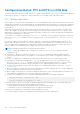
Table Of Contents
- Dell EMC Networking Configuration Guide for the C9010 Series Version 9.14.2.5
- About this Guide
- Configuration Fundamentals
- Getting Started
- Switch Management
- Configuring Privilege Levels
- Configuring Logging
- Track Login Activity
- Limit Concurrent Login Sessions
- Enabling Secured CLI Mode
- Log Messages in the Internal Buffer
- Disabling System Logging
- Sending System Messages to a Syslog Server
- Display the Logging Buffer and the Logging Configuration
- Changing System Logging Settings
- Configuring a UNIX Logging Facility Level
- Synchronizing Log Messages
- Enabling Timestamp on Syslog Messages
- File Transfer Services
- Terminal Lines
- Setting Time Out of EXEC Privilege Mode
- Using Telnet to Access Another Network Device
- Lock CONFIGURATION Mode
- LPC Bus Quality Degradation
- Recovering from a Forgotten Password
- Ignoring the Startup Configuration and Booting from the Factory-Default Configuration
- Recovering from a Failed Start
- Restoring Factory-Default Settings
- Using Hashes to Verify Software Images Before Installation
- Verifying System Images on C9010 Components
- Viewing the Reason for Last System Reboot
- 802.1X
- The Port-Authentication Process
- Configuring 802.1X
- Important Points to Remember
- Enabling 802.1X
- Configuring dot1x Profile
- Configuring MAC addresses for a do1x Profile
- Configuring the Static MAB and MAB Profile
- Configuring Critical VLAN
- Configuring Request Identity Re-Transmissions
- Configuring a Quiet Period after a Failed Authentication
- Forcibly Authorizing or Unauthorizing a Port
- Re-Authenticating a Port
- Configuring Dynamic VLAN Assignment with Port Authentication
- Guest and Authentication-Fail VLANs
- Multi-Host Authentication
- Multi-Supplicant Authentication
- MAC Authentication Bypass
- Dynamic CoS with 802.1X
- Access Control Lists (ACLs)
- IP Access Control Lists (ACLs)
- ACL Optimization to Increase Number of Supported IPv4 ACLs
- IP Fragment Handling
- Configure a Standard IP ACL
- Configure an Extended IP ACL
- Configure Layer 2 and Layer 3 ACLs
- Using ACL VLAN Groups
- Applying an IP ACL
- IP Prefix Lists
- ACL Remarks
- ACL Resequencing
- Route Maps
- Important Points to Remember
- Configuring a UDF ACL
- Hot-Lock Behavior
- Bidirectional Forwarding Detection (BFD)
- Border Gateway Protocol IPv4 (BGPv4)
- Autonomous Systems (AS)
- Sessions and Peers
- Route Reflectors
- BGP Attributes
- Multiprotocol BGP
- Implement BGP
- Configuration Information
- BGP Configuration
- Enabling BGP
- Configuring AS4 Number Representations
- Configuring Peer Groups
- Configuring BGP Fast Fail-Over
- Configuring Passive Peering
- Maintaining Existing AS Numbers During an AS Migration
- Allowing an AS Number to Appear in its Own AS Path
- Filtering on an AS-Path Attribute
- Regular Expressions as Filters
- Redistributing Routes
- Enabling Additional Paths
- Configuring IP Community Lists
- Configuring an IP Extended Community List
- Filtering Routes with Community Lists
- Manipulating the COMMUNITY Attribute
- Changing MED Attributes
- Changing the LOCAL_PREFERENCE Attribute
- Configuring the local System or a Different System to be the Next Hop for BGP-Learned Routes
- Changing the WEIGHT Attribute
- Enabling Multipath
- Filtering BGP Routes
- Filtering BGP Routes Using Route Maps
- Filtering BGP Routes Using AS-PATH Information
- Configuring BGP Route Reflectors
- Aggregating Routes
- Configuring BGP Confederations
- Enabling Route Flap Dampening
- Changing BGP Timers
- Setting the extended timer
- Enabling BGP Neighbor Soft-Reconfiguration
- Enabling or disabling BGP neighbors
- Route Map Continue
- Enabling MBGP Configurations
- BGP Regular Expression Optimization
- Debugging BGP
- Sample Configurations
- Content Addressable Memory (CAM)
- Control Plane Policing (CoPP)
- Data Center Bridging (DCB)
- Enabling Data Center Bridging
- Ethernet Enhancements in Data Center Bridging
- QoS dot1p Traffic Classification and Queue Assignment
- SNMP Support for PFC and Buffer Statistics Tracking
- DCB Maps and its Attributes
- Data Center Bridging: Default Configuration
- Configuration Notes: PFC and ETS in a DCB Map
- Configuring Priority-Based Flow Control
- Configuring Enhanced Transmission Selection
- Configure a DCBx Operation
- DCBx Operation
- DCBx Port Roles
- DCB Configuration Exchange
- Configuration Source Election
- Propagation of DCB Information
- Auto-Detection and Manual Configuration of the DCBx Version
- Behavior of Tagged Packets
- Configuration Example for DSCP and PFC Priorities
- DCBx Example
- DCBx Prerequisites and Restrictions
- Configuring DCBx
- Verifying the DCB Configuration
- Performing PFC Using DSCP Bits Instead of 802.1p Bits
- PFC and ETS Configuration Examples
- Using PFC and ETS to Manage Data Center Traffic
- Priority-Based Flow Control Using Dynamic Buffer Method
- Configuring the Dynamic Buffer Method
- Debugging and Diagnostics
- Dynamic Host Configuration Protocol (DHCP)
- DHCP Packet Format and Options
- Assign an IP Address using DHCP
- Implementation Information
- Configure the System to be a DHCP Server
- Configure the System to be a Relay Agent
- Configure the System to be a DHCP Client
- DHCP Relay When DHCP Server and Client are in Different VRFs
- Non-default VRF configuration for DHCPv6 helper address
- Configuring DHCP relay source interface
- Configure Secure DHCP
- Source Address Validation
- Equal Cost Multi-Path (ECMP)
- FCoE Transit
- FIPS Cryptography
- Flex Hash and Optimized Boot-Up
- Force10 Resilient Ring Protocol (FRRP)
- GARP VLAN Registration Protocol (GVRP)
- High Availability (HA)
- Internet Group Management Protocol (IGMP)
- Interfaces
- Port Numbering
- Interface Types
- View Basic Interface Information
- Resetting an Interface to its Factory Default State
- Enabling a Physical Interface
- Physical Interfaces
- Egress Interface Selection (EIS)
- Management Interfaces
- Port Extender Interfaces
- VLAN Interfaces
- Loopback Interfaces
- Null Interfaces
- Configuring Port Delay
- Port Channel Interfaces
- Port Channel Definition and Standards
- Port Channel Benefits
- Port Channel Implementation
- 10/40 Gbps Interfaces in Port Channels
- Configuration Tasks for Port Channel Interfaces
- Creating a Port Channel
- Adding a Physical Interface to a Port Channel
- Reassigning an Interface to a New Port Channel
- Configuring the Minimum Oper Up Links in a Port Channel
- Adding or Removing a Port Channel from a VLAN
- Assigning an IP Address to a Port Channel
- Deleting or Disabling a Port Channel
- Load Balancing Through Port Channels
- Changing the Hash Algorithm
- Bulk Configuration
- Defining Interface Range Macros
- Monitoring and Maintaining Interfaces
- Displaying Traffic Statistics on HiGig Ports
- Link Bundle Monitoring
- Monitoring HiGig Link Bundles
- Non Dell-Qualified Transceivers
- Splitting QSFP Ports to SFP+ Ports
- Configuring wavelength for 10–Gigabit SFP+ optics
- Link Dampening
- Using Ethernet Pause Frames for Flow Control
- Configure the MTU Size on an Interface
- Auto-Negotiation on Ethernet Interfaces
- Provisioning Combo Ports
- View Advanced Interface Information
- Configuring the Traffic Sampling Size Globally
- Dynamic Counters
- Internet Protocol Security (IPSec)
- IPv4 Routing
- IP Addresses
- Configuration Tasks for IP Addresses
- Assigning IP Addresses to an Interface
- Configuring Static Routes
- Configure Static Routes for the Management Interface
- Enabling Directed Broadcast
- Resolution of Host Names
- Enabling Dynamic Resolution of Host Names
- Specifying the Local System Domain and a List of Domains
- Configuring DNS with Traceroute
- ARP
- ICMP
- ICMP Redirects
- IPv6 Routing
- Protocol Overview
- IPv6 Implementation on the Dell Networking OS
- Configuring the LPM Table for IPv6 Extended Prefixes
- ICMPv6
- Path MTU Discovery
- IPv6 Neighbor Discovery
- Secure Shell (SSH) Over an IPv6 Transport
- Configuration Tasks for IPv6
- Adjusting Your CAM Profile
- Assigning an IPv6 Address to an Interface
- Assigning a Static IPv6 Route
- Configuring Telnet with IPv6
- SNMP over IPv6
- Displaying IPv6 Information
- Displaying an IPv6 Configuration
- Displaying IPv6 Routes
- Displaying the Running Configuration for an Interface
- Clearing IPv6 Routes
- Disabling ND Entry Timeout
- Configuring IPv6 RA Guard
- Intermediate System to Intermediate System
- IS-IS Protocol Overview
- IS-IS Addressing
- Multi-Topology IS-IS
- Graceful Restart
- Implementation Information
- Configuration Information
- IS-IS Metric Styles
- Configure Metric Values
- Sample Configurations
- iSCSI Optimization
- iSCSI Optimization Overview
- Default iSCSI Optimization Values
- iSCSI Optimization Prerequisites
- Configuring iSCSI Optimization
- Displaying iSCSI Optimization Information
- Enable and Disable iSCSI Optimization
- Synchronizing iSCSI Sessions Learned on VLT-Lags with VLT-Peer
- Monitoring iSCSI Traffic Flows
- Information Monitored in iSCSI Traffic Flows
- Detection and Auto-Configuration for Dell EqualLogic Arrays
- Configuring Detection and Ports for Dell Compellent Arrays
- Application of Quality of Service to iSCSI Traffic Flows
- Link Aggregation Control Protocol (LACP)
- Layer 2
- Manage the MAC Address Table
- MAC Learning Limit
- Setting the MAC Learning Limit
- mac learning-limit Dynamic
- mac learning-limit mac-address-sticky
- mac learning-limit station-move
- mac learning-limit no-station-move
- Learning Limit Violation Actions
- Setting Station Move Violation Actions
- Recovering from Learning Limit and Station Move Violations
- Disabling MAC Address Learning on the System
- Enabling port security
- NIC Teaming
- Configure Redundant Pairs
- Far-End Failure Detection
- Link Layer Discovery Protocol (LLDP)
- 802.1AB (LLDP) Overview
- Optional TLVs
- TIA-1057 (LLDP-MED) Overview
- Configure LLDP
- CONFIGURATION versus INTERFACE Configurations
- Enabling LLDP
- Enabling LLDP on Management Ports
- Advertising TLVs
- Storing and Viewing Unrecognized LLDP TLVs
- Viewing the LLDP Configuration
- Viewing Information Advertised by Adjacent LLDP Neighbors
- Configuring LLDPDU Intervals
- Configuring LLDP Notification Interval
- Configuring Transmit and Receive Mode
- Configuring a Time to Live
- Debugging LLDP
- Relevant Management Objects
- Multicast Source Discovery Protocol (MSDP)
- Anycast RP
- Implementation Information
- Configure Multicast Source Discovery Protocol
- Enable MSDP
- Manage the Source-Active Cache
- Accept Source-Active Messages that Fail the RFP Check
- Specifying Source-Active Messages
- Limiting the Source-Active Messages from a Peer
- Preventing MSDP from Caching a Local Source
- Preventing MSDP from Caching a Remote Source
- Preventing MSDP from Advertising a Local Source
- Logging Changes in Peership States
- Terminating a Peership
- Clearing Peer Statistics
- Debugging MSDP
- MSDP with Anycast RP
- Configuring Anycast RP
- MSDP Sample Configurations
- Multiple Spanning Tree Protocol (MSTP)
- Spanning Tree Variations
- Configure Multiple Spanning Tree Protocol
- Enable Multiple Spanning Tree Globally
- Adding and Removing Interfaces
- Creating Multiple Spanning Tree Instances
- Influencing MSTP Root Selection
- Interoperate with Non-Dell Bridges
- Changing the Region Name or Revision
- Modifying Global Parameters
- Modifying the Interface Parameters
- Configuring an EdgePort
- Flush MAC Addresses after a Topology Change
- MSTP Sample Configurations
- Debugging and Verifying MSTP Configurations
- Multicast Features
- Multicast Listener Discovery Protocol
- Object Tracking
- Open Shortest Path First (OSPFv2 and OSPFv3)
- Protocol Overview
- OSPF Implementation
- Configuration Information
- Configuration Task List for OSPFv2 (OSPF for IPv4)
- Enabling OSPFv2
- Assigning a Router ID
- Enabling Multi-Process OSPF (OSPFv2, IPv4 Only)
- Assigning an OSPFv2 Area
- Enable OSPFv2 on Interfaces
- Configuring Stub Areas
- Configuring LSA Throttling Timers
- Enabling Passive Interfaces
- Enabling Fast-Convergence
- Changing OSPFv2 Parameters on Interfaces
- Enabling OSPFv2 Authentication
- Creating Filter Routes
- Applying Prefix Lists
- Redistributing Routes
- Troubleshooting OSPFv2
- Configuration Task List for OSPFv2 (OSPF for IPv4)
- Sample Configurations for OSPFv2
- OSPFv3 NSSA
- Configuration Task List for OSPFv3 (OSPF for IPv6)
- Enabling IPv6 Unicast Routing
- Assigning IPv6 Addresses on an Interface
- Assigning Area ID on an Interface
- Assigning OSPFv3 Process ID and Router ID Globally
- Assigning OSPFv3 Process ID and Router ID to a VRF
- Configuring the Cost of OSPFv3 Routes
- Configuring Stub Areas
- Configuring Passive-Interface
- Redistributing Routes
- Configuring a Default Route
- OSPFv3 Authentication Using IPsec
- Troubleshooting OSPFv3
- MIB Support for OSPFv3
- Per-VLAN Spanning Tree Plus (PVST+)
- Protocol Overview
- Implementation Information
- Configure Per-VLAN Spanning Tree Plus
- Enabling PVST+
- Disabling PVST+
- Influencing PVST+ Root Selection
- Modifying Global PVST+ Parameters
- Modifying Interface PVST+ Parameters
- Configuring an EdgePort
- PVST+ in Multi-Vendor Networks
- Enabling PVST+ Extend System ID
- PVST+ Sample Configurations
- PIM Sparse-Mode (PIM-SM)
- PIM Source-Specific Mode (PIM-SSM)
- Policy-based Routing (PBR)
- Port Extenders (PEs)
- IEEE 802.1BR
- 802.1BR Terms and Definitions
- Enabling the Port Extender Feature
- Provisioning a Port Extender
- PE Selection Logic
- Managing a Port Extender
- Preventing Loops on Port Extender Ports
- Upgrading a Port Extender
- De-provisioning a Port Extender
- Scheduling PE reboots
- Troubleshooting a Port Extender
- Supported Features
- Dual Homing
- Port Extender (PE) Stacking
- Port Monitoring
- Power over Ethernet (PoE)
- Configuring PoE or PoE+
- Manage Ports using Power Priority and the Power Budget
- Setting the Threshold Limit for the PoE Power Budget
- Advertising the Extended Power through MDI
- Advertising Extended Power Though dot3–TLVs
- Detecting Legacy Devices and Allocating Power
- Deploying Voice Over IP (VoIP)
- Managing PoE on the Port Extender
- Private VLANs (PVLAN)
- Quality of Service (QoS)
- Implementation Information
- Port-Based QoS Configurations
- Policy-Based QoS Configurations
- DSCP Color Maps
- Enabling QoS Rate Adjustment
- Enabling Strict-Priority Queueing
- Weighted Random Early Detection
- Explicit Congestion Notification
- Using A Configurable Weight for WRED and ECN
- Pre-Calculating Available QoS CAM Space
- SNMP Support for Buffer Statistics Tracking
- Routing Information Protocol (RIP)
- Remote Monitoring (RMON)
- Rapid Spanning Tree Protocol (RSTP)
- Protocol Overview
- Configuring Rapid Spanning Tree
- Important Points to Remember
- Configuring Interfaces for Layer 2 Mode
- Enabling Rapid Spanning Tree Protocol Globally
- Adding and Removing Interfaces
- Modifying Global Parameters
- Modifying Interface Parameters
- Influencing RSTP Root Selection
- Configuring an EdgePort
- Configuring Fast Hellos for Link State Detection
- Security
- Role-Based Access Control
- AAA Accounting
- AAA Authentication
- AAA Authorization
- RADIUS
- RADIUS Authentication and Authorization
- Configuration Task List for RADIUS
- Support for Change of Authorization and Disconnect Messages packets
- Change of Authorization (CoA) packets
- Disconnect Messages
- Attributes
- Error-cause Values
- CoA Packet Processing
- CoA or DM Discard
- Disconnect Message Processing
- Configuring DAC
- Configuring the port number
- Configuring shared key
- Disconnecting administrative users logged in through RADIUS
- Configuring CoA to bounce 802.1x enabled ports
- Configuring CoA to re-authenticate 802.1x sessions
- Terminating the 802.1x user session
- Disabling 802.1x enabled port
- Important points to remember
- Configuring replay protection
- Rate-limiting RADIUS packets
- Configuring time-out value
- TACACS+
- Protection from TCP Tiny and Overlapping Fragment Attacks
- Enabling SCP and SSH
- Using SCP with SSH to Copy a Software Image
- Removing the RSA Host Keys and Zeroizing Storage
- Configuring When to Re-generate an SSH Key
- Configuring the SSH Server Cipher List
- Configuring DNS in the SSH Server
- Configuring the HMAC Algorithm for the SSH Server
- Configuring the HMAC Algorithm for the SSH Client
- Configuring the SSH Server Cipher List
- Configuring the SSH Client Cipher List
- Secure Shell Authentication
- Troubleshooting SSH
- Telnet
- VTY Line and Access-Class Configuration
- Two Factor Authentication (2FA)
- Configuring the System to Drop Certain ICMP Reply Messages
- Dell EMC Networking OS Security Hardening
- Service Provider Bridging
- sFlow
- Simple Network Management Protocol (SNMP)
- Protocol Overview
- Implementation Information
- Configuration Task List for SNMP
- Important Points to Remember
- Set up SNMP
- Reading Managed Object Values
- Writing Managed Object Values
- Configuring Contact and Location Information using SNMP
- Configuring the CPU Utilization for SNMP Traps
- Configuring Threshold Memory Utilization for SNMP Traps
- Subscribing to Managed Object Value Updates using SNMP
- Enabling a Subset of SNMP Traps
- Enabling an SNMP Agent to Notify Syslog Server Failure
- Copy Configuration Files Using SNMP
- Copying a Configuration File
- Copying Configuration Files via SNMP
- Copying the Startup-Config Files to the Running-Config
- Copying the Startup-Config Files to the Server via FTP
- Copying the Startup-Config Files to the Server via TFTP
- Copy a Binary File to the Startup-Configuration
- Additional MIB Objects to View Copy Statistics
- Obtaining a Value for MIB Objects
- MIB Support to Display Reason for Last System Reboot
- MIB Support to Display the Available Partitions on Flash
- MIB Support to Display Egress Queue Statistics
- MIB Support to Display Egress Queue Statistics
- MIB Support for entAliasMappingTable
- SNMP Support for WRED Green/Yellow/Red Drop Counters
- MIB Support for LAG
- MIB Support to Display Unrecognized LLDP TLVs
- MIB support for Port Security
- Manage VLANs using SNMP
- Managing Overload on Startup
- Enabling and Disabling a Port using SNMP
- Fetch Dynamic MAC Entries using SNMP
- Deriving Interface Indices
- Monitoring BGP sessions via SNMP
- Monitor Port-Channels
- Troubleshooting SNMP Operation
- Transceiver Monitoring
- Configuring SNMP context name
- Storm Control
- Spanning Tree Protocol (STP)
- Protocol Overview
- Configure Spanning Tree
- Important Points to Remember
- Configuring Interfaces for Layer 2 Mode
- Enabling Spanning Tree Protocol Globally
- Adding an Interface to the Spanning Tree Group
- Modifying Global Parameters
- Modifying Interface STP Parameters
- Enabling PortFast
- Prevent Network Disruptions with BPDU Guard
- Selecting STP Root
- STP Root Guard
- Enabling SNMP Traps for Root Elections and Topology Changes
- STP Loop Guard
- Displaying STP Guard Configuration
- SupportAssist
- System Time and Date
- Tunneling
- Upgrade Procedures
- Uplink Failure Detection (UFD)
- Virtual LANs (VLANs)
- VLT Proxy Gateway
- Virtual Routing and Forwarding (VRF)
- Virtual Link Trunking (VLT)
- Overview
- VLT Terminology
- Important Points to Remember
- Configuration Notes
- Primary and Secondary VLT Peers
- RSTP and VLT
- VLT Bandwidth Monitoring
- VLT and High Availability
- VLT and IGMP Snooping
- VLT and Stacking
- VLT IPv6
- VLT Port Delayed Restoration
- PIM-Sparse Mode Support on VLT
- VLT Routing
- Non-VLT ARP Sync
- RSTP Configuration
- Configuring VLT
- Configuring a VLT Interconnect
- Enabling VLT and Creating a VLT Domain
- Configuring a VLT Backup Link
- Configuring a VLT Port Delay Period
- Reconfiguring the Default VLT Settings (Optional)
- Connecting a VLT Domain to an Attached Access Device (Switch or Server)
- Configuring a VLT VLAN Peer-Down (Optional)
- Configuring Enhanced VLT (eVLT) (Optional)
- VLT Sample Configuration
- eVLT Configuration Example
- PIM-Sparse Mode Configuration Example
- Verifying a VLT Configuration
- Additional VLT Sample Configurations
- Troubleshooting VLT
- Reconfiguring Stacked Switches as VLT
- Specifying VLT Nodes in a PVLAN
- Configuring a VLT VLAN or LAG in a PVLAN
- Proxy ARP Capability on VLT Peer Nodes
- VLT Nodes as Rendezvous Points for Multicast Resiliency
- Configuring VLAN-Stack over VLT
- Configure BFD in VLT Domain
- Virtual Router Redundancy Protocol (VRRP)
- VRRP Overview
- VRRP Benefits
- VRRP Implementation
- VRRP Configuration
- Configuration Task List
- Creating a Virtual Router
- Configuring the VRRP Version for an IPv4 Group
- Assign Virtual IP addresses
- Configuring a Virtual IP Address
- Setting VRRP Group (Virtual Router) Priority
- Configuring VRRP Authentication
- Disabling Preempt
- Changing the Advertisement Interval
- Setting VRRP Initialization Delay
- Track an Interface or Object
- Tracking an Interface
- Configuration Task List
- Sample Configurations
- Proxy Gateway with VRRP
- Standards Compliance
- X.509v3
- Introduction to X.509v3 certification
- X.509v3 support in Dell Networking OS
- Information about installing CA certificates
- Information about Creating Certificate Signing Requests (CSR)
- Information about installing trusted certificates
- Transport layer security (TLS)
- Online certificate status protocol (OSCP)
- Verifying certificates
- Event logging

● If you configure more than one priority group as strict priority, the higher numbered priority queue is given preference when
scheduling data traffic.
Configuring Priority-Based Flow Control
Priority-Based Flow Control (PFC) provides a flow control mechanism based on the 802.1p priorities in converged Ethernet
traffic received on an interface and is enabled by default when you enable DCB.
As an enhancement to the existing Ethernet pause mechanism, PFC stops traffic transmission for specified priorities (Class of
Service (CoS) values) without impacting other priority classes. Different traffic types are assigned to different priority classes.
When traffic congestion occurs, PFC sends a pause frame to a peer device with the CoS priority values of the traffic that is
to be stopped. Data Center Bridging Exchange protocol (DCBx) provides the link-level exchange of PFC parameters between
peer devices. PFC allows network administrators to create zero-loss links for Storage Area Network (SAN) traffic that requires
no-drop service, while retaining packet-drop congestion management for Local Area Network (LAN) traffic.
To configure PFC, follow these steps.
1. Create a DCB Map.
CONFIGURATION mode
dcb-map dcb-map-name
The dcb-map-name variable can have a maximum of 32 characters.
2. Create a priority group.
CONFIGURATION mode
priority-group group-num {bandwidth bandwidth | strict-priority} [[committed | peak]
bandwidth [burst-size] [peak | committed] bandwidth [burst-size]] pfc {on | off}
The range for priority group is from 0 to 7.
Set the bandwidth in percentage. The percentage range is from 1 to 100% in units of 1%.
Committed and peak bandwidth is in megabits per second. The range is from 0 to 40000.
Committed and peak burst size is in kilobytes. Default is 50. The range is from 0 to 10000.
The pfc on command enables priority-based flow control.
3. Specify the dot1p priority-to-priority group mapping for each priority.
priority-pgid dot1p0_group_num dot1p1_group_num ...dot1p7_group_num
Priority group range is from 0 to 7. All priorities that map to the same queue must be in the same priority group.
Leave a space between each priority group number. For example: priority-pgid 0 0 0 1 2 4 4 4 in which priority group 0 maps
to dot1p priorities 0, 1, and 2; priority group 1 maps to dot1p priority 3; priority group 2 maps to dot1p priority 4; priority group
4 maps to dot1p priorities 5, 6, and 7.
Dell Networking OS Behavior: As soon as you apply a DCB policy with PFC enabled on an interface, DCBx starts exchanging
information with PFC-enabled peers. The IEEE802.1Qbb, CEE, and CIN versions of PFC Type, Length, Value (TLV) are
supported. DCBx also validates PFC configurations that are received in TLVs from peer devices.
NOTE: You cannot enable PFC and link-level flow control at the same time on an interface.
Dell Networking OS does not support MACsec Bypass Capability (MBC).
NOTE:
We recommend that you do not use the dcb-policy input, dcb-policy output, dcb-input, dcb-
output, and priority-group commands as those are removed from Release 9.6.(0.0).
Configuring Lossless Queues
DCB also supports the manual configuration of lossless queues on an interface when PFC mode is turned off.
Prerequisite: A DCB with PFC configuration is applied to the interface with the following conditions:
● PFC mode is off (no pfc mode on).
● No PFC priority classes are configured (no pfc priority priority-range).
The configuration of no-drop queues provides flexibility for ports on which PFC is not needed but lossless traffic should egress
from the interface.
256
Data Center Bridging (DCB)