
Glossary

Pause and Resume of Traffic
The pause message is used by the sending device to inform the receiving device about a congested, heavily-loaded traffic state
that has been identified. When the interface of a sending device transmits a pause frame, the recipient acknowledges this frame
by temporarily halting the transmission of data packets. The sending device requests the recipient to restart the transmission of
data traffic when the congestion eases and reduces. The time period that is specified in the pause frame defines the duration
for which the flow of data packets is halted. When the time period elapses, the transmission restarts.
When a device sends a pause frame to another device, the time for which the sending of packets from the other device must be
stopped is contained in the pause frame. The device that sent the pause frame empties the buffer to be less than the threshold
value and restarts the acceptance of data packets.
Dynamic ingress buffering enables the sending of pause frames at different thresholds based on the number of ports that
experience congestion at a time. This behavior impacts the total buffer size used by a particular lossless priority on an interface.
The pause and resume thresholds can also be configured dynamically. You can configure a buffer size, pause threshold, ingress
shared threshold weight, and resume threshold to control and manage the total amount of buffers that are to be used in your
network environment.
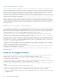
Buffer Sizes for Lossless or PFC Packets
You can configure up to a maximum of 4 lossless (PFC) queues. By configuring 4 lossless queues, you can configure 4 different
priorities and assign a particular priority to each application that your network is used to process. For example, you can assign a
higher priority for time-sensitive applications and a lower priority for other services, such as file transfers. You can configure the
amount of buffer space to be allocated for each priority and the pause or resume thresholds for the buffer. This method of
configuration enables you to effectively manage and administer the behavior of lossless queues.
Although the system contains of space for shared buffers, a minimum guaranteed buffer is provided to all the internal and
external ports in the system for both unicast and multicast traffic. This minimum guaranteed buffer reduces the total available
shared buffer to . This shared buffer can be used for lossy and lossless traffic.
The default behavior causes up to a maximum of 6.6 MB to be used for PFC-related traffic. The remaining approximate space of
1 MB can be used by lossy traffic. You can allocate all the remaining 1 MB to lossless PFC queues. If you allocate in such a way,
the performance of lossy traffic is reduced and degraded. Although you can allocate a maximum buffer size, it is used only if a
PFC priority is configured and applied on the interface.
The number of lossless queues supported on the system is dependent on the availability of total buffers for PFC. The default
configuration in the system guarantees a minimum of 52 KB per queue if all the 128 queues are congested. However, modifying
the buffer allocation per queue impacts this default behavior.
By default the total available buffer for PFC is 6.6 MB and when you configure dynamic ingress buffering, a minimum of least 52
KB per queue is used when all ports are congested.
This default behavior is impacted if you modify the total buffer available for PFC or assign static buffer configurations to the
individual PFC queues.
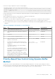
Behavior of Tagged Packets
The below is example for enabling PFC for priority 2 for tagged packets. Priority (Packet Dot1p) 2 will be mapped to PG6 on
PRIO2PG setting. All other Priorities for which PFC is not enabled are mapped to default PG – PG7.
Classification rules on ingress (Ingress FP CAM region) matches incoming packet-dot1p and assigns an internal priority (to
select queue as per Table 1 and Table 2).
The internal Priority assigned for the packet by Ingress FP is used by the memory management unit (MMU) to assign the packet
to right queue by indexing the internal-priority to queue map table (TABLE 1) in hardware.
PRIO2COS setting for honoring the PFC protocol packets from the Peer switches is as per above Packet-Dot1p->queue table
(Table 2).
The packets come in with packet-dot1p 2 alone are assign to PG6 on ingress.
The packets come in with packet-dot1p 2 alone use Q1 (as per dot1p to Queue classification – Table 2) on the egress port.
● When Peer sends a PFC message for Priority 2, based on above PRIO2COS table (TABLE 2), Queue 1 is halted.
● Queue 1 starts buffering the packets with Dot1p 2. This causes PG6 buffer counter to increase on the ingress, since P-dot1p
2 is mapped to PG6.
262
Data Center Bridging (DCB)