
Deployment Guide


● Prevent Network Disruptions with BPDU Guard
● Influencing RSTP Root Selection
● Configuring Spanning Trees as Hitless
● Enabling SNMP Traps for Root Elections and Topology Changes
● Configuring Fast Hellos for Link State Detection
● Flush MAC Addresses after a Topology Change
Important Points to Remember
● RSTP is disabled by default.
● Dell EMC Networking OS supports only one Rapid Spanning Tree (RST) instance.
● All interfaces in virtual local area networks (VLANs) and all enabled interfaces in Layer 2 mode are automatically added to the
RST topology.
● Adding a group of ports to a range of VLANs sends multiple messages to the rapid spanning tree protocol (RSTP) task, avoid
using the range command. When using the range command, Dell EMC Networking recommends limiting the range to five
ports and 40 VLANs.
RSTP and VLT
Virtual link trunking (VLT) provides loop-free redundant topologies and does not require RSTP.
RSTP can cause temporary port state blocking and may cause topology changes after link or node failures. Spanning tree
topology changes are distributed to the entire Layer 2 network, which can cause a network-wide flush of learned media access
control (MAC) and address resolution protocol (ARP) addresses, requiring these addresses to be re-learned. However, enabling
RSTP can detect potential loops caused by non-system issues such as cabling errors or incorrect configurations. RSTP is useful
for potential loop detection but to minimize possible topology changes after link or node failure, configure it using the following
specifications.
The following recommendations help you avoid these issues and the associated traffic loss caused by using RSTP when you
enable VLT on both VLT peers:
● Configure any ports at the edge of the spanning tree’s operating domain as edge ports, which are directly connected to end
stations or server racks. Ports connected directly to Layer 3-only routers not running STP should have RSTP disabled or be
configured as edge ports.
● Ensure that the primary VLT node is the root bridge and the secondary VLT peer node has the second-best bridge ID in the
network. If the primary VLT peer node fails, the secondary VLT peer node becomes the root bridge, avoiding problems with
spanning tree port state changes that occur when a VLT node fails or recovers.
● Even with this configuration, if the node has non-VLT ports using RSTP that are not configured as edge ports and are
connected to other layer 2 switches, spanning tree topology changes can still be detected after VLT node recovery. To avoid
this scenario, ensure that you configure any non-VLT ports as edge ports or have RSTP disabled.
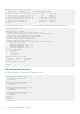
Configuring Interfaces for Layer 2 Mode
To configure and enable interfaces in Layer 2 mode, use the following commands.
All interfaces on all bridges that participate in Rapid Spanning Tree must be in Layer 2 and enabled.
1. If the interface has been assigned an IP address, remove it.
INTERFACE mode
no ip address
2. Place the interface in Layer 2 mode.
INTERFACE mode
switchport
3. Enable the interface.
INTERFACE mode
no shutdown
Rapid Spanning Tree Protocol (RSTP)
749