
Deployment Guide

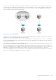
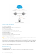
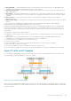
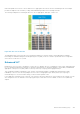
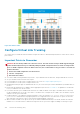
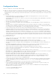

Figure 132. Example of VLT Deployment
VLT offers the following benefits:
● Allows a single device to use a LAG across two upstream devices.
● Eliminates STP-blocked ports.
● Provides a loop-free topology.
● Uses all available uplink bandwidth.
● Provides fast convergence if either the link or a device fails.
● Optimized forwarding with virtual router redundancy protocol (VRRP).
● Provides link-level resiliency.
● Assures high availability.
● Active-Active load sharing with VRRP.
● Active-Active load sharing with peer-routing for Layer-3 VLAN
● Graceful failover of LACP during reload
● Agility in VM Migration under VLT domain.
CAUTION:
Dell EMC Networking does not recommend enabling Stacking and VLT simultaneously. If you enable
both features at the same time, unexpected behavior may occur.
As shown in the following example, VLT presents a single logical Layer 2 domain from the perspective of attached devices that
have a virtual link trunk terminating on separate chassis in the VLT domain. However, the two VLT chassis are independent
Layer2/Layer3 (L2/L3) switches for devices in the upstream network. L2/L3 control plane protocols and system management
features function normally in VLT mode. Features such as VRRP and internet group management protocol (IGMP) snooping
require state information coordinating between the two VLT chassis. IGMP and VLT configurations must be identical on both
sides of the trunk to ensure the same behavior on both sides.
The following example shows how VLT is deployed. The switches appear as a single virtual switch from the point of view of the
switch or server supporting link aggregation control protocol (LACP).
VLT Terminology
The following are key VLT terms.
● Virtual link trunk (VLT) — The combined port channel between an attached device and the VLT peer switches.
944
Virtual Link Trunking (VLT)