User’s Guide Dell P2214H Dell P2414H Model No.
Notes, Cautions, and Warnings NOTE: A NOTE indicates important information that helps you make better use of your computer. CAUTION: A CAUTION indicates potential damage to hardware or loss of data if instructions are not followed. WARNING: A WARNING indicates a potential for property damage, personal injury, or death. ____________________ Information in this document is subject to change without notice. © 2013-2016 Dell Inc. All rights reserved.
Contents 1 About Your Monitor . . . . . . . . . . . . . . . . . . . . . . Package Contents . . . . . . . . . . . . . Product Features . . . . . . . . . . . . . . Identifying Parts and Controls . . . . . Monitor Specifications . . . . . . . . . . Universal Serial Bus (USB) Interface . LCD Monitor Quality and Pixel Policy 2 Setting Up the Monitor . . . . . . . . . . 5 6 7 10 18 19 . . . . . . . . . . . . . . . . . . 21 Attaching the Stand . . . . . . . Connecting Your Monitor . . .
Setting Up Your Monitor 4 | Contents . . . . . . . . . . . . . . . . . . .
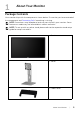
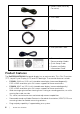
1 About Your Monitor Package Contents Your monitor ships with the components shown below. Ensure that you have received all the components and Contacting Dell if something is missing. NOTE: Some items may be optional and may not ship with your monitor. Some features or media may not be available in certain countries. NOTE: To set up with any other stand, please refer to the respective stand setup guide for setup instructions.
• Power Cable (Varies by Countries) • VGA Cable • DP Cable • USB Upstream Cable • Drivers and Documentation Media • Quick Setup Guide • Product and Safety Information Guide Product Features The Dell P2214H/P2414H flat panel display has an active matrix, Thin-Film Transistor (TFT), Liquid Crystal Display (LCD) and LED backlight. The monitor features include: 6 • P2214H: 54.61 cm (21.5-inch) viewable area display (measured diagonally).
• On-Screen Display (OSD) adjustments for ease of set-up and screen optimization. • Software and documentation media includes an Information File (INF), Image Color Matching File (ICM), and product documentation. • Dell Display Manager Software included (comes in the CD shipped with the monitor). • Security lock slot. • Stand lock. • Capability to switch from wide aspect to standard aspect ratio while maintaining the image quality.
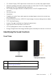
Back View Back View with monitor stand Label 8 Description Use 1 VESA mounting holes (100 mm x 100 mm - behind attached VESA Cover) Wall mount monitor using VESAcompatible wall mount kit (100 mm x 100 mm). 2 Regulatory label Lists the regulatory approvals. 3 Stand release button Release stand from monitor. 4 Security lock slot Secures monitor with security lock (security lock not included).
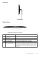
Side View Bottom View Bottom view without monitor stand Label Description Use 1 AC power cord connector Connect the power cable. 2 DP connector Connect your computer with DP cable. 3 DVI connector Connect your computer with DVI cable. 4 VGA connector Connect your computer with VGA cable. 5 USB upstream port Connect the USB cable that came with your monitor to the monitor and the computer. Once this cable is connected, you can use the USB connectors on the monitor.
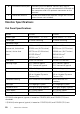
6 USB downstream port Connect your USB device. You can only use this connector after you have connected the USB cable to the computer and USB upstream connector on the monitor. 7 Stand lock feature To lock the stand to the monitor using a M3 x 6 mm screw (screw not included). Monitor Specifications Flat Panel Specifications Model P2214H P2414H Screen type Active matrix - TFT LCD Active matrix - TFT LCD Panel type In Plane Switching In Plane Switching Diagonal 54.61 cm (21.5 inches) 60.
standards.
Electrical Specifications Model P2214H/P2414H • Analog RGB, 0.7 Volts +/- 5%, positive polarity at 75 ohm input impedance • Digital DVI-D TMDS, 600 mV for each differential line, positive polarity at 50 ohm input impedance • DP 1.2 signal input support* Video input signals Synchronization input signals Separate horizontal and vertical synchronizations, polarity-free TTL level, SOG (Composite SYNC on green) AC input voltage/frequency/ current 100 VAC to 240 VAC / 50 Hz or 60 Hz + 3 Hz / 1.
Width 512.7 mm (20.19 inches) 565.6 mm (22.27 inches) Depth 180.0 mm (7.09 inches) 180.0 mm (7.09 inches) Height 304.4 mm (11.98 inches) 335.1 mm (13.19 inches) Width 512.7 mm (20.19 inches) 565.6 mm (22.27 inches) Depth 46.3 mm (1.82 inches) 47.0 mm (1.85 inches) Height (extended) 399.7 mm (15.74 inches) 399.7 mm (15.74 inches) Height (compressed) 354.2 mm (13.94 inches) 354.2 mm (13.94 inches) Width 225.0 mm (8.86 inches) 225.0 mm (8.86 inches) Depth 180.0 mm (7.09 inches) 180.
Non-operating 12,192m (40,000 ft) (maximum) Thermal dissipation • 143.3 BTU/hour (maximum) • 88.7 BTU/hour (typical) • 153.5 BTU/hour (maximum) • 95.5 BTU/hour (typical) Power Management Modes If you have VESA's DPM™ compliance display card or software installed in your PC, the monitor can automatically reduce its power consumption when not in use. This is referred to as Power Save Mode*.
ordered and shall have no obligation to update such information. Accordingly, the customer should not rely upon this information in making decisions about electrical tolerances or otherwise. No warranty as to accuracy or completeness is expressed or implied. Pin Assignments VGA Connector Pin Number 15-pin Side of the Connected Signal Cable 1 Video-Red 2 Video-Green 3 Video-Blue 4 GND 5 Self-test 6 GND-R 7 GND-G 8 GND-B 9 Computer 5 V/3.
DVI Connector Pin Number 16 24-pin Side of the Connected Signal Cable 1 TMDS RX2- 2 TMDS RX2+ 3 TMDS Ground 4 Floating 5 Floating 6 DDC Clock 7 DDC Data 8 Floating 9 TMDS RX1- 10 TMDS RX1+ 11 TMDS Ground 12 Floating 13 Floating 14 +5 V/+3.
DisplayPort Connector Pin Number 20-pin Side of the Connected Signal Cable 1 ML0(p) 2 GND 3 ML0(n) 4 ML1(p) 5 GND 6 ML1(n) 7 ML2(p) 8 GND 9 ML2(n) 10 ML3(p) 11 GND 12 ML3(n) 13 GND 14 GND 15 AUX(p) 16 GND 17 AUX(n) 18 GND 19 Re-PWR 20 PWR About Your Monitor | 17
Plug and Play Capability You can install the monitor in any Plug and Play-compatible system. The monitor automatically provides the computer system with its Extended Display Identification Data (EDID) using Display Data Channel (DDC) protocols so the system can configure itself and optimize the monitor settings. Most monitor installations are automatic; you can select different settings if desired. For more information about changing the monitor settings, see Operating the Monitor.
USB Downstream Connector Pin Number 4-pin Side of the Connector 1 VCC 2 DMD 3 DPD 4 GND USB Ports • 1 upstream - back • 4 downstream - back NOTE: USB 2.0 functionality requires a USB 2.0-capable computer. NOTE: The monitor's USB interface works only when the monitor is On or in the power save mode. If you turn Off the monitor and then turn it On, the attached peripherals may take a few seconds to resume normal functionality.
Maintenance Guidelines Cleaning Your Monitor CAUTION: Read and follow the Safety Instructions before cleaning the monitor. WARNING: Before cleaning the monitor, unplug the monitor power cable from the electrical outlet. For best practices, follow the instructions in the list below while unpacking, cleaning, or handling your monitor: 20 • To clean your anti-static screen, lightly dampen a soft, clean cloth with water.
2 Setting Up the Monitor Attaching the Stand NOTE: The stand is detached when the monitor is shipped from the factory. NOTE: This is applicable for a monitor with a stand. When any other stand is bought, please refer to the respective stand setup guide for the set up instructions. To attach the monitor stand: 1. Remove the cover and place the monitor on it. 2. Fit the two tabs on the upper part of the stand to the groove on the back of the monitor. 3. Press the stand till it snaps into place.
Connecting the blue VGA cable Connecting the white DVI cable Connecting the black DisplayPort cable CAUTION: The graphics are used for the purpose of illustration only. Appearance of the computer may vary.
Connecting the USB cable After you have completed connecting the VGA/DVI/DP cable, follow the procedures below to connect the USB cable to the computer and complete your monitor setup: 1. Connect the upstream USB port (cable supplied) to an appropriate USB port on your computer. (See Bottom View for details.) 2. Connect the USB peripherals to the downstream USB ports on the monitor. 3. Plug the power cables for your computer and monitor into a nearby outlet. 4. Turn on the monitor and the computer.
Attaching the Cable Cover The Cable Cover is detached when the monitor is shipped from the factory. 1. Fit the two tabs on the bottom part of the Cable Cover to the groove on the back of the monitor. 2. Press the Cable Cover till it snaps into place. Removing the Monitor Stand NOTE: To prevent scratches on the LCD screen while removing the stand, ensure that the monitor is placed on a soft, clean surface. NOTE: This is applicable for a monitor with a stand.
Wall Mounting (Optional) (Screw dimension: M4 x 10 mm). Refer to the instructions that come with the VESA-compatible wall mounting kit. 1. Place the monitor panel on a soft cloth or cushion on a stable, flat table. 2. Remove the stand. 3. Use a Phillips crosshead screwdriver to remove the four screws securing the plastic cover. 4. Attach the mounting bracket from the wall mounting kit to the monitor. 5.
| Setting Up the Monitor
3 Operating the Monitor Power On the Monitor Press the button to turn on the monitor. Using the Front Panel Controls Use the control buttons on the front of the monitor to adjust the characteristics of the image being displayed. As you use these buttons to adjust the controls, an OSD shows the numeric values of the characteristics as they change. The following table describes the front panel buttons: Front Panel Button 1 Description Use this button to choose from a list of preset color modes.
Use this button to directly access the Brightness/Contrast menu. 2 Shortcut key/ Brightness/ Contrast Use the MENU button to launch the On-Screen Display (OSD) and select the OSD Menu. See Accessing the Menu System. 3 Menu 4 Use this button to go back to the main menu or exit the OSD main menu. Exit Use the Power button to turn the monitor On and Off. 5 Power (with power light indicator) The white light indicates the monitor is On and fully functional.
Use the OK button to confirm your selection. 3 OK Use the Back button to go back to the previous menu. 4 Back Using the On-Screen Display (OSD) Menu Accessing the Menu System NOTE: If you change the settings and then either proceed to another menu or exit the OSD menu, the monitor automatically saves those changes. The changes are also saved if you change the settings and then wait for the OSD menu to disappear. 1. Press the button to launch the OSD menu and display the main menu.
Main Menu for digital (DVI) input or Main Menu for digital (DP) input NOTE: Auto Adjust is only available when you use the analog (VGA) connector. 2. Press the and buttons to move between the setting options. As you move from one icon to another, the option name is highlighted. See the following table for a complete list of all the options available for the monitor. 3. Press the 4. Press 30 | button once to activate the highlighted option. and button to select the desired parameter.
5. Press to enter the slide bar and then use the and to the indicators on the menu, to make your changes. 6. Select the buttons, according button to return to the main menu.
Icon Menu and Submenus Description Brightness/ Use this menu to activate Brightness/Contrast adjustment. Contrast Brightness Brightness adjusts the luminance of the backlight. Press the button to increase the brightness and press the button to decrease the brightness (min. 0 / max 100). NOTE: Manual adjustment of Brightness is disabled when Energy Smart or Dynamic Contrast is switched on. Contrast Adjust the Brightness first, and then adjust the Contrast only if further adjustment is necessary.
Input Source Use the Input Source menu to select between the different video signals that may be connected to your monitor. Auto Select Press to select Auto Select, the monitor scans for available input sources. VGA Select the VGA input when you are using the analog (VGA) connector. Press to select the VGA input source. DVI-D Select the DVI-D input when you are using the Digital (DVI) connector. Press to select the DVI input source.
Color Settings Use Color Settings to adjust the color setting mode. Input Color Allows you to set the video input mode to: Format RGB: Select this option if your monitor is connected to a computer or DVD player using the VGA and DVI cable. YPbPr: Select this option if your monitor is connected to a DVD player by YPbPr to VGA, or YPbPr to DVI cable; or if the DVD color output setting is not RGB.
Preset Modes When you select Preset Modes, you can choose Standard, Multimedia, Movie, Game, Text, Warm, Cool or Custom Color from the list. • Standard: Loads the monitor's default color settings. This is the default preset mode. • Multimedia: Loads color settings ideal for multimedia applications. • Movie: Loads color settings ideal for movies. • Game: Loads color settings ideal for most gaming applications. • Text: Loads brightness and sharpness settings ideal for viewing texts.
Image Enhance Makes upsized images higher quality by removing image fading and roughness of edge. NOTE: Image Enhance is available only when you select Standard, Multimedia, Movie, or Game preset mode. Reset Color Reset your monitor color settings to the factory settings. Settings Display Settings Use the Display Settings to adjust image. Aspect Ratio Adjusts the image ratio to Wide 16:9, 4:3, or 5:4. Horizontal Position Use Vertical Position Use or to adjust the image left or right.
Energy Settings Energy Smart To turn on or off dynamic dimming. The dynamic dimming feature automatically reduces the screen's brightness level when the displayed image contains a high proportion of bright areas. Allows you to set the power LED indicator on or off to save energy. Power Button LED USB Allows you to enable or disable USB function during monitor standby mode. NOTE: USB ON/OFF under standby mode is only available when the USB upstream cable is unplugged.
Menu Settings Select this option to adjust the settings of the OSD, such as, the languages of the OSD, the amount of time the menu remains on screen, and so on. Language Language options set the OSD display to one of the eight languages (English, Spanish, French, German, Brazilian Portuguese, Russian, Simplified Chinese or Japanese). Rotation Rotates the OSD by 90 degrees counter-clockwise. You can adjust the menu according to your Display Rotation.
Other Settings DDC/CI DDC/CI (Display Data Channel/Command Interface) allows your monitor parameters (brightness, color balance, and etc.) to be adjustable via the software on your computer. You can disable this feature by selecting Disable. Enable this feature for best user experience and optimum performance of your monitor.
Helps reduce minor cases of image retention. Depending on the LCD Conditioning degree of image retention, the program may take some time to run. You can enable this feature by selecting Enable. Reset Other Reset all settings under the Other Settings menu to the factory preset values. Settings Factory Reset Reset all settings to the factory preset values.
OSD Warning Messages When the Energy Smart or Dynamic Contrast feature is enabled (in these preset modes: Game or Movie), the manual brightness adjustment is disabled. When the monitor does not support a particular resolution mode, you will see the following message: This means that the monitor cannot synchronize with the signal that it is receiving from the computer. See Monitor Specifications for the Horizontal and Vertical frequency ranges addressable by this monitor. Recommended mode is 1920 x 1080.
When the monitor enters the Power Save mode, the following message appears: Activate the computer and wake up the monitor to gain access to the OSD. If you press any button other than the power button, one of the following messages will appear depending on the selected input: VGA/DVI-D/DP input If either VGA, DVI-D, or DP input is selected and the corresponding cable is not connected, a floating dialog box as shown below appears.
or See Troubleshooting for more information. Setting the Maximum Resolution To set the maximum resolution for the monitor: In Windows® 7, Windows® 8, and Windows® 8.1: 1. For Windows® 8 and Windows® 8.1 only, select the Desktop tile to switch to classic desktop. 2. Right-click on the desktop and click Screen Resolution. 3. Click the Dropdown list of the Screen Resolution and select 1920 x 1080. 4. Click OK. In Windows® 10: 1. Right-click on the desktop and click Display settings. 2.
Using the Tilt, Swivel, and Vertical Extension NOTE: This is applicable for a monitor with a stand. When any other stand is bought, please refer to the respective stand setup guide for set up instructions. Tilt, Swivel With the stand attached to the monitor, you can tilt and swivel the monitor for the most comfortable viewing angle. NOTE: The stand is detached when the monitor is shipped from the factory. Vertical Extension NOTE: The stand extends vertically up to 130 mm.
Rotating the Monitor Before you rotate the monitor, your monitor should be fully vertically extended (Vertical Extension) and fully tilted up to avoid hitting the bottom edge of the monitor. To use the Display Rotation function (Landscape versus Portrait view) with your Dell computer, you require an updated graphics driver that is not included with this monitor. To download the graphics driver, go to www.dell.com/support and see the Download section for Video Drivers for latest driver updates.
Adjusting the Rotation Display Settings of Your System After you have rotated your monitor, you need to complete the procedure below to adjust the Rotation Display Settings of your system. If you are using the monitor with a non-Dell computer, you need to go the graphics driver website or your computer manufacturer website for information on rotating the 'contents' on your display. To adjust the Rotation Display Settings: 1. Right-click on the desktop and click Properties. 2.
4 Troubleshooting WARNING: Before you begin any of the procedures in this section, follow the Safety Instructions. Self-Test Your monitor provides a self-test feature that allows you to check whether your monitor is functioning properly. If your monitor and computer are properly connected but the monitor screen remains dark, run the monitor self-test by performing the following steps: 1. Turn off both your computer and the monitor. 2. Unplug the video cable from the back of the computer.
or 4. This box also appears during normal system operation, if the video cable becomes disconnected or damaged. 5. Turn off your monitor and reconnect the video cable; then turn on both your computer and the monitor. If your monitor screen remains blank after you use the previous procedure, check your video controller and computer, because your monitor is functioning properly.
3. Press and hold Button 1 and Button 4 on the front panel simultaneously for 2 seconds. A gray screen appears. 4. Carefully inspect the screen for abnormalities. 5. Press Button 4 on the front panel again. The color of the screen changes to red. 6. Inspect the display for any abnormalities. 7. Repeat steps 5 and 6 to inspect the display in green, blue, black, white and text screens. The test is complete when the text screen appears. To exit, press Button 4 again.
Missing Pixels LCD screen has spots • Cycle power on-off. • Pixel that is permanently off is a natural defect that can occur in LCD technology. • For more information on Dell Monitor Quality and Pixel Policy, see Dell Support site at:http://www.dell.com/ support/monitors. Stuck-on Pixels LCD screen has bright spots • Cycle power on-off. • Pixel that is permanently off is a natural defect that can occur in LCD technology.
Missing Color Picture missing color • Perform monitor self-test feature check. • Ensure that the video cable connecting the monitor to the computer is connected properly and is secure. • Check for bent or broken pins in the video cable connector. Wrong Color Picture color not good • Change the Color Setting Mode in the Color Settings OSD to Graphics or Video depending on the application. • Try different Color Preset Settings in Color Settings OSD.
Universal Serial Bus (USB) Specific Problems Specific Symptoms What You Experience Possible Solutions USB interface is USB peripherals not working are not working • • • • • • High Speed USB 2.0 interface is slow • Check that your computer is USB 2.0-capable. • Some computers have both USB 2.0 and USB 1.1 ports. Ensure that the correct USB port is used. • Reconnect the upstream cable to your computer. • Reconnect the USB peripherals (downstream connector). • Reboot the computer.
5 Appendix WARNING: Safety Instructions WARNING: Use of controls, adjustments, or procedures other than those specified in this documentation may result in exposure to shock, electrical hazards, and/or mechanical hazards. For information on safety instructions, see the Product Information Guide. FCC Notices (U.S. Only) and Other Regulatory Information For FCC notices and other regulatory information, see the regulatory compliance website located at www.dell.com\regulatory_compliance.
1. For Windows® 8 and Windows® 8.1 only, select the Desktop tile to switch to classic desktop. 2. Right-click on the desktop and click Screen Resolution. 3. Click the Dropdown list of the Screen Resolution and select 1920 x 1080. 4. Click OK. In Windows® 10: 1. Right-click on the desktop and click Display settings. 2. Click Advanced display settings. 3. Click the dropdown list of Resolution and select 1920 x 1080. 4. Click Apply.
In Windows® 10: 1. Right-click on the desktop and click Display settings. 2. Click Advanced display settings. 3. Click the dropdown list of Resolution and select 1920 x 1080. 4. Identify your graphics controller supplier from the description at the top of the window (e.g. NVIDIA, ATI, Intel etc.). 5. Refer to the graphic card provider website for updated driver (for example, http://www.ATI.com OR http://www.NVIDIA.com). 6.