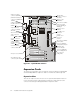
This chapter describes how to install the following options: Peripheral Component Interconnect (PCI) expansion cards System memory Microprocessors This chapter also includes instructions for replacing the system battery, if necessary. Use Figure 8-1 to locate the system board features. support.dell.
main power input connector (POWER_1) diskette-drive interface connector (FLOPPY) parallel and serial port connectors (PARALLEL/ SERIAL) battery socket (BATTERY) IDE connector (IDE1) voltage regulator module connector (VRM1) memory module sockets (DIMM_A– DIMM_D) keyboard/mouse connectors (KYBD/ MOUSE) microprocessor (PROC1) secondary SCSI connector (SCSI2) fan connector (FAN1) USB connectors (USB) primary SCSI connector (SCSI1) monitor connector (VGA) fan connector (FAN2) voltage regulator modul
Follow this general procedure to install an expansion card: 1. Prepare the expansion card for installation, and remove the computer cover according to the instructions in “Removing the Computer Cover” in Chapter 7.
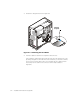
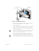
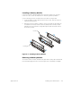
3. Unlatch the card guide as shown in Figure 8-3. unlatching card guide 4. Insert the expansion card into the expansion-card connector. If the expansion card is full-length, insert the front end of the card into the corresponding card guide on the inside front of the chassis as you insert the card into its connector. Insert the card's edge connector firmly into the expansion-card slot.
expansion card connector card-edge connector expansion card ! " #$% 5. When the card is firmly seated in the connector, secure the card's mounting bracket to the chassis with the screw you removed in step 2. 6. Close the card guide latch. 7. Connect any cables that should be attached to the card. See the documentation that came with the card for information about the card's cable connections. 8.
Follow this general procedure to remove an expansion card: 1. Remove the computer cover according to the instructions in “Removing the Computer Cover” in Chapter 7. 2. If necessary, disconnect any cables connected to the card. 3. Unscrew the mounting bracket of the card you want to remove. 4. Unlatch the card guide. 5.
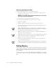
DIMM_A DIMM_D memory module socket front of computer & ' ' When adding system memory, you may install memory modules in any order. For optimum operation, Dell recommends installing the memory modules starting with socket A (closest to the top edge of the system board) and working toward socket D, leaving no open sockets between installed memory modules. Table 8-1 lists sample memory configurations.
2. To access the memory module sockets on the system board, rotate the power supply as described in “Rotating the Power Supply Away From the System Board” in Chapter 7. 3. Determine the memory module sockets in which you will install memory modules or replace existing memory modules. 4. Install or replace memory modules as necessary to reach the desired memory total. Follow the instructions in “Installing a Memory Module” or “Removing a Memory Module,” later in this chapter as appropriate. 5.
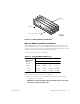
If a memory module is already installed in the socket you want to use, you must remove it. To do so, follow the instructions in “Removing a Memory Module.” Use the following procedure to install a memory module (see Figure 8-6): 1. Locate the plastic securing clips at each end of the socket. Press the clips outward until they snap open. 2.
securing clip - ' ' To take advantage of future options in speed and functionality, you can add a second processor or replace either the primary or secondary processor. ! " ! Each processor and its associated L-2 cache memory are contained in a Flip Chip Pin Grid Array (FC-PGA) package that is installed in a zero insertion force (ZIF) socket on the system board.
NOTE: Dell recommends that only a technically knowledgeable person perform this procedure. 1. Remove the computer cover according to the instructions in “Removing the Computer Cover,” in Chapter 7. 2. Rotate the power supply as described in “Rotating the Power Supply Away From the System Board,” in Chapter 7. 3.
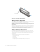
# $ ! $ % ! ! ! $ ! % ! & ! ' ( ) ! % " ! * ! + ! ! " press here to release securing clip / % 5. Remove the heat sink. 6. Remove the microprocessor chip from the socket.
microprocessor chip microprocessor socket release lever 7. 0 ' % Unpack the new microprocessor. If any of the pins on the microprocessor appear bent, see Chapter 10, “Getting Help,” for instructions on obtaining technical assistance from Dell. # + " , % ! ! % + ! ! ! 8.
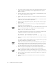
9. Install the microprocessor chip in the socket (see Figure 8-12). # ! ! ! ! , ! If the release lever on the microprocessor socket is not all the way up, move it to that position now. With the pin-1 corners of the chip and socket aligned, set the chip lightly in the socket and make sure all pins are matched with the correct holes in the socket.
securing clip heat sink microprocessor chip microprocessor socket " 2 12. If you are adding a second microprocessor, disconnect the FAN1 connector and place the VRM in the socket (see Figure 8-14). Make sure that the latches engage. VRM socket VRM latches support.dell.
13. Connect the FAN1 connector. 14. Replace the air shroud. 15. Replace the computer cover making sure that the shroud support holds the shroud in place. 16. Reconnect your computer and peripherals to their power sources, and turn them on. 17. Press to enter the System Setup program, and check that the PROCESSOR 1 and PROCESSOR 2 categories match the new system configuration. See the system User’s Guide for instructions. 18.
The operating life of the battery can extend up to 10 years.
4. Locate the battery and remove it. The battery is mounted in a socket labeled "BATTERY" (see Figure 8-1).
9. While in the System Setup program, reset the chassis intrusion detector, and then exit the System Setup program. NOTE: If a setup password has been assigned by someone else, contact your network administrator for information on resetting the chassis intrusion detector. 10. Turn off your computer, and unplug it for at least 10 minutes. 11. After 10 minutes, plug in the computer, turn it on, and enter the System Setup program.
8-20 Installation and Troubleshooting Guide