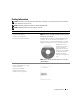
Dell™ XPS™ 210 Owner’s Manual front panel door (open) optional floppy drive or Media Card Reader* diagnostic lights hard drive activity light front panel door (push to open) headphone connector CD or DVD drive light microphone connector USB 2.
Notes, Notices, and Cautions NOTE: A NOTE indicates important information that helps you make better use of your computer. NOTICE: A NOTICE indicates either potential damage to hardware or loss of data and tells you how to avoid the problem. CAUTION: A CAUTION indicates a potential for property damage, personal injury, or death. If you purchased a Dell™ n Series computer, any references in this document to Microsoft® Windows® operating systems are not applicable.
Contents Finding Information 1 . . . . . . . . . . . . . . . . . . . . . . . . . . . . . . . . Setting Up and Using Your Computer . . . . . . . . . . . . . . . . 13 . . . . . . . . . . . . . . . . . . . . . 13 . . . . . . . . . . . . . . . . . . . . . . . . . . . . . . . . . . . . . . . . . . . . . . . . . . . . . . . . 13 15 16 . . . . . . . . . . . . . . . . . . . . . . . . . . . . . . . 17 Front and Back View of the Computer . Front View . . . . . . Back View . . . . . .
Intel® Viiv™ Technology (Optional) . . . . . . . . . . . . . . . . . . . . . . . Using Intel® Viiv™ Quick Resume Technology (Optional) Enabling the QRT Feature in System Setup . . . . . . . . Enabling the QRT feature in the Operating system . . . . . . . . . . . . . . . . . . . . . . . . . . . . . . . 31 . . . . . . . . . . . . . . . . . . . . . . . . . . . . . 33 . . . . . . . . . . . . . . . . . . . . . . . . . . . . . . 33 . . . . . . . . . . . . . . . . . . . . . . . . . . . . . . . . 33 . .
Sound and Speaker Problems . . . . . . . . . . . . . . . . . . . . . . . . . . Video and Monitor Problems . . . . . . . . . . . . . . . . . . . . . . . . . . . . . . . . . . . . . . . . . . . . . . . . . . 47 . . . . . . . . . . . . . . . . . . . . . . . . . . . . . . . . . . . . . . . . . . . . . . . 47 48 . . . . . . . . . . . . . . . . . . . . . . . . . . 49 . . . . . . . . . . . . . . . . . . . . . . . . . . . . . . . . 49 . . . . . . . . . . . . . . . . . . . . . . . . . . . . . . . . .
Cards . . . . . . . . . . . . . . . . . . . . . . . . . . . . . . . . . . . . . . . Drives . . . . . . . . . . . . . . . . . . . . . . . . . . . . . . . . . . . . . . . . . . . . . . . . . . . . . . . . . . . . . . . . . . . . . . . . . . . . . . . . . . . . . . . . . . 76 CD/DVD Drive. . . . . . . . . . . . . . . . . . . . . . . . . . . . . . . . . . . 81 . . . . . . . . . . . . . . . . . . . . . . . . . 81 83 . . . . . . . . . . . . . . . . . . . . . . . . . . . . . . . 85 . . . . . . . . .
Cleaning Your Computer . . . . . . . . . . . . . . . . . . . . . . . . . . . . Computer, Keyboard, and Monitor Mouse . . . . . . . . . . . . . . . CDs and DVDs . . . . . . . . . . . . . . . . . . . . . . . . . . . . . . . . . . . . . . . . . . . . . . . . . . . . . . . . . . . . . . . . . . . . . . . Dell Technical Support Policy (U.S. Only) . . . . . . . . . . . . . . . . . . . 109 110 110 110 . . . . . . . . . 111 111 . . . . . . . . . . . . . . . . . . . . . . . . . . . . 111 . . . . . . . . .
Contents
Finding Information NOTE: Some features or media may be optional and may not ship with your computer. Some features or media may not be available in certain countries. NOTE: This Owner’s Manual is available as a PDF at support.dell.com. NOTE: Additional information may ship with your computer. What Are You Looking For? Find It Here • • • • Drivers and Utilities CD (ResourceCD) NOTE: The Drivers and Utilities CD may be optional and may not ship with your computer.
What Are You Looking For? Find It Here • How to set up my computer Setup Diagram • Service Tag and Express Service Code • Microsoft® Windows® Product Key Label Service Tag and Microsoft Windows Product Key These labels are located on your computer. • Use the Service Tag to identify your computer when you use support.dell.com or contact support. • Enter the Express Service Code to direct your call when contacting support.
What Are You Looking For? Find It Here • Solutions — Troubleshooting hints and tips, articles from technicians, online courses, and frequently asked questions • Community — Online discussion with other Dell customers • Upgrades — Upgrade information for components, such as the memory, hard drive, and operating system • Customer Care — Contact information, service call and order status, and warranty and repair information • Service and support — Service call status, support history, service contract, and o
What Are You Looking For? Find It Here • How to reinstall my operating system Operating System CD NOTE: The Operating System CD may be optional and may not ship with your computer. The operating system is already installed on your computer. To reinstall your operating system see "Restoring Your Operating System" on page 56. After you reinstall your operating system, use the Drivers and Utilities CD (ResourceCD) to reinstall drivers for the devices that came with your computer.
Setting Up and Using Your Computer Front and Back View of the Computer Front View NOTE: The front panel door does not close when you are using the Flash Media, IEEE 1394, USB, or headphone connectors.
1 CD/DVD drive eject button Press this button to eject a CD/DVD from the drive. 2 CD/DVD drive-activity light The drive activity light is on when the computer reads data from the CD or DVD drive. 3 USB 2.0 connectors (2) Use the front USB connectors for devices that you connect occasionally, such as joysticks or cameras (see "System Setup" on page 101 for more information on booting to a USB device).
Back View 1 2 3 4 1 voltage selection switch See the safety instructions in the Product Information Guide for more information. 2 power connector Insert the power cable. 3 back panel connectors Plug IEEE 1394, USB and other devices into the appropriate connector. 4 card slots Access connectors for any installed PCI Express cards.
Back I/O Connectors 1 2 3 5 4 6 7 14 13 12 11 10 9 8 1 link integrity light • Green — A good connection exists between a 10-Mbps network and the computer. • Orange — A good connection exists between a 100-Mbps network and the computer. • Off — The computer is not detecting a physical connection to the network. 2 network adapter connector To attach your computer to a network or broadband device, connect one end of a network cable to either a network jack or your network or broadband device.
microphone 8 Use the pink connector to attach a personal computer microphone for voice or musical input into a sound or telephony program. On computers with a sound card, the microphone connector is on the card. 9 side surround sound connector Use the grey surround sound connector to attach multichannel-capable speakers. 10 center/LFE connector LFE (Low Frequency Effects) Audio channel found in digital surround sound audio schemes that carries only low frequency information of 80 Hz and below.
Connecting a USB Printer NOTE: You can connect USB devices while the computer is turned on. 1 Complete the operating system setup, if you have not already done so. 2 Install the printer driver if necessary. See the documentation that came with your printer. 3 Attach the USB printer cable to the USB connectors on the computer and the printer. The USB connectors fit only one way.
• MultiMediaCard (MMC) • Reduced size MMC • Memory Stick (MS/MS Pro/Duo Pro) For information on installing a Media Card Reader, see "Installing a Media Card Reader" on page 87. 1 2 3 4 1 xD-Picture Card and SmartMedia (SMC) 2 CompactFlash Type I and II (CF I/II) and MicroDrive Card 3 Memory Stick (MS/MS Pro) 4 SecureDigital Card (SD)/ MultiMediaCard (MMC) To use the Media Card Reader: 1 Check the media or card to determine the proper orientation for insertion.
Connecting a TV (Optional) NOTE: To connect a TV to your computer, you must have a video card that has TV-out functionality and an S-video cable, which is available at most consumer electronics stores. An S-video cable is not included with your computer. 1 Follow the procedures in "Before You Begin" on page 61. 2 Connect one end of the S-video cable to the TV-OUT connector on the back of the computer. 3 Connect the other end of the S-video cable to the S-video input connector on your TV.
1 2 3 2 1 network adapter connector on computer 2 network adapter connector 3 network cable 4 network device Network Setup Wizard The Microsoft® Windows® XP operating system provides a Network Setup Wizard to guide you through the process of sharing files, printers, or an Internet connection between computers in a home or small office. 1 Click the Start button, point to All Programs→ Accessories→ Communications, and then click Network Setup Wizard. 2 On the welcome screen, click Next.
Connecting to the Internet NOTE: ISPs and ISP offerings vary by country. To connect to the Internet, you need a modem or network connection and an Internet service provider (ISP), such as AOL or MSN. Your ISP will offer one or more of the following Internet connection options: • Dial-up connections that provide Internet access through a telephone line. Dial-up connections are considerably slower than DSL and cable modem connections.
6 Click the appropriate option under How do you want to connect to the Internet?, and then click Next. NOTE: If you do not know which type of connection to select, contact your ISP. 7 Use the setup information provided by your ISP to complete the setup. If you are having problems connecting to the Internet, see "E-Mail, Modem, and Internet Problems" on page 35. If you cannot connect to the Internet, but have successfully connected in the past, the ISP might have a service outage.
To format CDs for storing data, to create music CDs, or to copy CDs, see the CD software that came with your computer. NOTE: Ensure that you observe all copyright laws when creating CDs or DVDs. A CD player includes the following basic buttons: Play. Move backward within the current track. Pause. Move forward within the current track. Stop. Go to the previous track. Eject. Go to the next track. A DVD player includes the following basic buttons: Stop. Play. Fast forward. Pause. Fast reverse.
Adjusting the Volume NOTE: When the speakers are muted, you do not hear the CD or DVD playing. 1 Click the Start button, point to All Programs→ Accessories→ Entertainment, and then click Volume Control. 2 In the Volume Control window, click the bar in the Volume Control column and slide it up or down to increase or decrease the volume. For more information on volume control options, click Help in the Volume Control window.
1 Click the Start button, point to All Programs→ Roxio→ Creator Projects, and then click RecordNow Copy. 2 Under the Copy tab, click Disc Copy. 3 To copy the CD or DVD: • If you have one CD/DVD drive, ensure that the settings are correct and click the Disc Copy button. The computer reads your source CD or DVD and copies the data to a temporary folder on your computer hard drive. When prompted, insert a blank CD or DVD into the drive and click OK.
DVD-Writable Drives Media Type Read Write Rewritable CD-R Yes Yes No CD-RW Yes Yes Yes DVD+R Yes Yes No DVD-R Yes Yes No DVD+RW Yes Yes Yes DVD-RW Yes Yes Yes DVD+R DL Yes Yes No Helpful Tips • Use Microsoft® Windows® Explorer to drag and drop files to a CD-R or CD-RW only after you start Roxio Creator Plus and open a Creator project. • Use CD-Rs to burn music CDs that you want to play in regular stereos. CD-RWs may not play in many home or car stereos.
Power Management The Microsoft® Windows® XP power management features can reduce the amount of electricity your computer uses when it is on and you are not using it. You can reduce power to just the monitor or the hard drive, or you can use standby mode or hibernate mode to reduce power to the entire computer. When the computer exits from a power conservation mode, the Windows desktop is restored to the state it was in before it entered the mode.
Because hibernate mode requires a special file on your hard drive with enough disk space to store the contents of the computer memory, Dell creates an appropriately sized hibernate mode file before shipping the computer to you. If the computer’s hard drive becomes corrupted, Windows XP recreates the hibernate file automatically. Power Options Properties Define your standby mode settings, hibernate mode settings, and other power settings in the Power Options Properties window.
Advanced Tab The Advanced tab allows you to: • Place the power options icon in the Windows taskbar for quick access. • Set the computer to prompt you for your Windows password before the computer exits from standby mode or hibernate mode. • Program the power button to activate standby mode, activate hibernate mode, or turn off the computer. To program these functions, click an option from the corresponding drop-down menu and click OK.
Enabling the QRT Feature in System Setup The QRT drivers must be installed before this feature becomes active. These drivers are installed when this option is ordered. Also, Quick Resume is enabled in system setup when this feature is ordered. 1 Enter system setup (see page 102). 2 Press the arrow keys to highlight the Power Management menu option, then press to access the menu. 3 Press the up- and down-arrow keys to highlight the Quick Resume option, then press to access the menu.
To determine if your computer is using Hyper-Threading technology: 1 Click the Start button, right-click My Computer, and then click Properties. 2 Click Hardware, then click Device Manager. 3 In the Device Manager window, click the plus (+) sign next to Processors. If Hyper-Threading is enabled, the processor is listed twice. You can enable or disable Hyper-Threading through system setup. For more information on accessing system setup, see "Entering System Setup" on page 102.
Solving Problems Troubleshooting Tips Follow these tips when you troubleshoot your computer: • If you added or removed a part before the problem started, review the installation procedures and ensure that the part is correctly installed. • If a peripheral device does not work, ensure that the device is properly connected. • If an error message appears on the screen, write down the exact message. This message may help technical support personnel diagnose and fix the problem(s).
Drive Problems CAUTION: Before you begin any of the procedures in this section, follow the safety instructions located in the Product Information Guide. E N S U R E T H A T M I C R O S O F T ® W I N D O W S ® R E C O G N I Z E S T H E D R I V E — Click the Start button, then click My Computer. If the floppy, CD, or DVD drive, is not listed, perform a full scan with your antivirus software to check for and remove viruses. Viruses can sometimes prevent Windows from recognizing the drive.
Problems writing to a CD/DVD-RW drive C L O S E O T H E R P R O G R A M S — The CD/DVD-RW drive must receive a steady stream of data during the writing process. If the stream is interrupted, an error occurs. Try closing all programs before you write to the CD/DVD-RW.
CHECK THE TELEPHONE LINE CONNECTION — CHECK THE TELEPHONE JACK — CONNECT THE MODEM DIRECTLY TO THE TELEPHONE WALL JACK — USE A DIFFERENT TELEPHONE LINE — • Verify that the telephone line is connected to the jack on the modem (the jack has either a green label or a connector-shaped icon next to it). • Ensure that you hear or feel a click when you insert the telephone line connector into the modem. • Disconnect the telephone line from the modem and connect it to a telephone. Listen for a dial tone.
Error Messages CAUTION: Before you begin any of the procedures in this section, follow the safety instructions located in the Product Information Guide. If the error message is not listed, see the documentation for the operating system or the program that was running when the message appeared. A F I L E N A M E C A N N O T C O N T A I N A N Y O F T H E F O L L O W I N G C H A R A C T E R S : \ / : * ? “ < > | — Do not use these characters in filenames. A R E Q U I R E D .
Media Card Reader Problems CAUTION: Before you begin any of the procedures in this section, follow the safety instructions located in the Product Information Guide. NO DRIVE LETTER IS ASSIGNED — When Microsoft Windows XP detects the Media Card Reader, the device is automatically assigned a drive letter as the next logical drive after all other physical drives in the system.
Keyboard Problems CAUTION: Before you begin any of the procedures in this section, follow the safety instructions located in the Product Information Guide. CHECK THE KEYBOARD CABLE — • Ensure that the keyboard cable is firmly connected to the computer. • Reconnect the keyboard cable as shown on the setup diagram for your computer. • Ensure that the cable is not damaged or frayed and check cable connectors for bent or broken pins. Straighten any bent pins.
A program stops responding END THE PROGRAM — 1 Press simultaneously to access the Windows Task Manager. 2 Click the Applications tab. 3 Click to select the program that is no longer responding. 4 Click End Task. A program crashes repeatedly NOTE: Most software includes installation instructions in its documentation or on a floppy disk or CD. C H E C K T H E S O F T W A R E D O C U M E N T A T I O N — If necessary, uninstall and then reinstall the program.
Other software problems CHECK THE SOFTWARE DOCUMENTATION OR CONTACT THE SOFTWARE MANUFACTURER FOR TROUBLESHOOTING INFORMATION — • Ensure that the program is compatible with the operating system installed on your computer. • Ensure that your computer meets the minimum hardware requirements needed to run the software. See the software documentation for information. • Ensure that the program is installed and configured properly. • Verify that the device drivers do not conflict with the program.
IF YOU EXPERIENCE OTHER MEMORY PROBLEMS — • Reseat the memory modules (see "Memory" on page 66) to ensure that your computer is successfully communicating with the memory. • Ensure that you are following the memory installation guidelines (see "Installing Memory" on page 68). • Ensure that the memory you are using is supported by your computer. For more information about the type of memory supported by your computer, see "Memory" on page 66. • Run the Dell Diagnostics (see "Dell Diagnostics" on page 52).
R U N T H E H A R D W A R E TR O U B L E S H O O T E R — See "Resolving Software and Hardware Incompatibilities" on page 56. Network Problems CAUTION: Before you begin any of the procedures in this section, follow the safety instructions located in the Product Information Guide. C H E C K T H E N E T W O R K C A B L E C O N N E C T O R — Ensure that the network cable is firmly inserted into the network connector on the back of the computer and the network jack.
I F T H E P O W E R L I G H T I S O F F — The computer is either turned off or is not receiving power. • Reseat the power cable in the power connector on the back of the computer and the electrical outlet. • Bypass power strips, power extension cables, and other power protection devices to verify that the computer turns on properly. • Ensure that any power strips being used are plugged into an electrical outlet and are turned on.
CHECK THE PRINTER CABLE CONNECTIONS — • See the printer documentation for cable connection information. • Ensure that the printer cables are securely connected to the printer and the computer (see "Printer Cable" on page 17). TE S T T H E E L E C T R I C A L O U T L E T — Ensure that the electrical outlet is working by testing it with another device, such as a lamp.
VE R I F Y T H A T T H E S C A N N E R I S R E C O G N I Z E D B Y M I C R O S O F T W I N D O W S — 1 Click Start, click Control Panel, and then click Printers and Other Hardware. 2 Click Scanners and Cameras. If your scanner is listed, Windows recognizes the scanner. R E I N S T A L L T H E S C A N N E R D R I V E R — See the scanner documentation for information on reinstalling the scanner driver.
R U N T H E S P E A K E R D I A G N O S T I C S — See your speaker documentation for more information. R E I N S T A L L T H E S O U N D D R I V E R — See "Reinstalling Drivers" on page 55. R U N T H E H A R D W A R E TR O U B L E S H O O T E R — See "Resolving Software and Hardware Incompatibilities" on page 56.
TE S T T H E E L E C T R I C A L O U T L E T — Ensure that the electrical outlet is working by testing it with another device, such as a lamp. C H E C K T H E D I A G N O S T I C L I G H T S — See "Diagnostic Lights" on page 49. The screen is difficult to read C H E C K T H E M O N I T O R S E T T I N G S — See the monitor documentation for instructions on adjusting the contrast and brightness, demagnetizing (degaussing) the monitor, and running the monitor self-test.
Troubleshooting Tools Diagnostic Lights CAUTION: Before you begin any of the procedures in this section, follow the safety instructions located in the Product Information Guide. To help you troubleshoot a problem, your computer has four lights labeled 1, 2, 3, and 4 on the front panel (see "Front View" on page 13). When the computer starts normally, the lights flash before turning off. If the computer malfunctions, the sequence of the lights identify the problem.
Light Pattern 50 Problem Description Suggested Resolution A possible graphics card failure has occurred. • Reseat any installed graphics cards (see "Cards" on page 70). • If available, install a working graphics card into your computer. • If the problem persists or the computer has integrated graphics, contact Dell (see "Contacting Dell" on page 112). A possible floppy drive or hard drive failure has occurred. Reseat all power and data cables. A possible USB failure has occurred.
Light Pattern Problem Description A possible expansion card failure has occurred. Suggested Resolution 1 Determine if a conflict exists by removing an expansion card (not a graphics card) and restarting the computer (see "Cards" on page 70). 2 If the problem persists, reinstall the card that you removed, then remove a different card and restart the computer. 3 Repeat this process for each expansion card installed.
Dell Diagnostics CAUTION: Before you begin any of the procedures in this section, follow the safety instructions located in the Product Information Guide. When to Use the Dell Diagnostics If you experience a problem with your computer, perform the checks in "Solving Problems" on page 33 and run the Dell Diagnostics before you contact Dell for technical assistance. NOTE: The Dell Diagnostics only operate on Dell computers. Starting the Dell Diagnostics 1 Turn on (or restart) your computer.
Dell Diagnostics Main Menu The following tests can be run from the Dell Diagnostics Main Menu: Option Function Express Test Performs a quick test of system devices. The test typically takes 10 to 20 minutes and requires no interaction on your part. Run Express Test first to increase the possibility of tracing the problem quickly. Extended Test Performs a thorough check of system devices. The test typically takes an hour or more and peridocially requires your input to answer specific questions.
Drivers What Is a Driver? A driver is a program that controls a device such as a printer, mouse, or keyboard. All devices require a driver program. A driver acts like a translator between the device and any other programs that use the device. Each device has its own set of specialized commands that only the driver for that device recognizes. Required drivers are already installed on your computer—no further installation or configuration is needed.
Reinstalling Drivers NOTICE: The Dell Support website at support.dell.com provides approved drivers for your Dell™ computer. If you install drivers obtained from other sources, your computer may not function properly. Using Windows XP Device Driver Rollback If a problem occurs on your computer after you install or update a driver, use Windows XP Device Driver Rollback to replace the driver with the previously installed version. 1 Click Start, then click Control Panel.
If Device Driver Rollback and manually reinstalling the driver do not resolve the problem, use System Restore to return your computer to the operating state that existed before you installed the new driver (see "Using Microsoft Windows XP System Restore" on page 56). Resolving Software and Hardware Incompatibilities If a device is either not detected during the operating system setup or is detected but incorrectly configured, you can use the Hardware Troubleshooter to resolve the incompatibility.
Restoring the Computer to an Earlier Operating State NOTICE: Before you restore the computer to an earlier operating state, save and close any open files and exit any open programs. Do not alter, open, or delete any files or programs until the system restoration process is complete. NOTE: If a problem occurs after you install a device driver, first try to resolve the problem by using Windows XP Device Driver Rollback (see "Using Windows XP Device Driver Rollback" on page 55).
Enabling System Restore If you reinstall Windows XP with less than 200 MB of free hard-disk space available, System Restore is automatically disabled. To determine if System Restore is enabled: 1 Click Start, then click Control Panel. 2 Under Pick a Category, click Performance and Maintenance. 3 Click System. 4 In the System Properties window, click the System Restore tab. 5 Ensure that Turn off System Restore is unchecked. NOTE: To disable System Restore, check Turn off System Restore.
7 Click Next. The System Restore screen appears and the computer restarts. 8 After the computer restarts, click OK. Removing Dell PC Restore NOTICE: Removing Dell PC Restore from the hard drive permanently deletes the PC Restore utility from your computer. After you have removed Dell PC Restore, you will not be able to use it to restore your computer’s operating system. Dell PC Restore enables you to restore your hard drive to the operating state it was in when you purchased your computer.
Troubleshooting Tools
Removing and Installing Parts Before You Begin This chapter provides procedures for removing and installing the components in your computer. Unless otherwise noted, each procedure assumes that the following conditions exist: • You have performed the steps in "Turning Off Your Computer" on page 61 and "Before Working Inside Your Computer" on page 62. • You have read the safety information in your Dell™ Product Information Guide.
Before Working Inside Your Computer Use the following safety guidelines to help protect your computer from potential damage and to help ensure your own personal safety. CAUTION: Before you begin any of the procedures in this section, follow the safety instructions located in the Product Information Guide. CAUTION: Handle components and cards with care. Do not touch the components or contacts on a card. Hold a card by its edges or by its metal mounting bracket.
3 Disconnect your computer and all attached devices from their electrical outlets, and then press the power button to ground the system board. CAUTION: To guard against electrical shock, always unplug your computer from the electrical outlet before opening the cover. NOTICE: Ensure that sufficient space exists to support the removed cover—at least 30 cm (1 ft) of desktop space.
Inside View of Your Computer CAUTION: Before you begin any of the procedures in this section, follow the safety instructions located in the Product Information Guide. CAUTION: To guard against electrical shock, always unplug your computer from the electrical outlet before opening the cover.
System Board Components 1 2 3 30 4 29 28 5 27 26 6 25 7 8 9 10 24 11 12 23 13 22 21 20 19 18 17 16 15 14 Removing and Installing Parts 65
1 processor fan connector (CPUFAN) 16 17 modem connector (RJ11) 2 processor connector (CPU) 3 processor power connector (POWER12V) 18 video connector (VGA) RJ11 internal connector (RJ11INT) 4 memory module connectors (2, 4) 19 Media Card Reader connector (USBINT) 5 memory module connectors (1, 3) 20 USB connectors (4) (USB_BACK) 6 battery socket (BATTERY) 21 network connector (NIC) and USB connectors (2) (NIC_USB1) 7 internal speaker (SPKR) 22 back-panel IEEE 1394 connector (BACK139
The recommended memory configurations are: • A pair of matched memory modules installed in DIMM connectors 1 and 2 (white securing clips) or • A pair of matched memory modules installed in DIMM connectors 1 and 2 and another matched pair installed in DIMM connectors 3 and 4 (black securing clips) NOTICE: Do not install ECC memory modules. • If you install mixed pairs of DDR2 800-MHz (PC2-6400) and DDR2 533-MHz (PC2-4300) memory, the modules function at the speed of the slowest module installed.
Addressing Memory With 4-GB Configurations Your computer supports a maximum of 4 GB of memory when you use two 2-GB DIMMs. Current operating systems, such as Microsoft® Windows® XP, can use a maximum of 4 GB of address space; however, the amount of memory available to the operating system is less than 4 GB. Certain components within the computer require address space in the 4-GB range. Any address space reserved for these components cannot be used by computer memory.
5 Align the notch on the bottom of the module with the crossbar in the connector. 1 3 4 2 1 notch 2 crossbar 3 memory module 4 cutouts (2) NOTICE: To avoid damage to the memory module, press the module straight down into the connector while you apply equal force to each end of the module. 6 Insert the module into the connector until the module snaps into position. If you insert the module correctly, the securing clips snap into the cutouts at each end of the module.
Removing Memory CAUTION: Before you begin any of the procedures in this section, follow the safety instructions located in the Product Information Guide. NOTICE: To prevent static damage to components inside your computer, discharge static electricity from your body before you touch any of your computer’s electronic components. You can do so by touching an unpainted metal surface on the computer chassis. 1 Follow the procedures in "Before You Begin" on page 61.
If you are installing or replacing a PCI Express card, follow the procedures in the next section. If you are removing but not replacing a card, see "Removing a PCI Express Card" on page 74. If you are replacing a card, remove the current driver for the card from the operating system. Installing a PCI Express Card 1 Follow the procedures in "Before You Begin" on page 61. 2 Gently push the release tab on the card retention door from the inside to pivot the door open.
5 Prepare the card for installation. See the documentation that came with the card for information on configuring the card, making internal connections, or otherwise customizing it for your computer. CAUTION: Some network adapters automatically start the computer when they are connected to a network. To guard against electrical shock, be sure to unplug your computer from its electrical outlet before installing any cards. 6 Place the card in the connector and press down firmly.
10 Close the card retention door by snapping it into place. 1 2 3 4 1 retention arm 2 PCI Express card 3 edge connector 4 card connector NOTICE: Do not route card cables over or behind the cards. Cables routed over the cards can prevent the computer cover from closing properly or cause damage to the equipment. 11 Connect any cables that should be attached to the card. See the documentation that came with the card for information about the card’s cable connections.
Removing a PCI Express Card 1 Follow the procedures in "Before You Begin" on page 61. 2 If necessary, disconnect any cables connected to the card. 3 Gently pull back the securing tab, grasp the card by its top corners, and then ease it out of its connector. 4 If you are removing the card permanently, install a filler bracket in the empty card-slot opening. NOTE: Installing filler brackets over empty card-slot openings is necessary to maintain FCC certification of the computer.
Connecting Drive Cables When you install a drive, you connect two cables—a DC power cable and a data cable—or a single interface cable to the back of the drive and to the system board. Drive Interface Connectors Most interface connectors are keyed for correct insertion; that is, a notch or a missing pin on one connector matches a tab or a filled-in hole on the other connector. Serial ATA cables go to the pin-1 end of the connector.
Connecting and Disconnecting Drive Cables When connecting and disconnecting a serial ATA data cable, hold the cable by the black connector at each end. The serial ATA interface connectors are keyed for correct insertion; that is, a notch or a missing pin on one connector matches a tab or a filled-in hole on the other connector. Hard Drive CAUTION: Before you begin any of the procedures in this section, follow the safety instructions located in the Product Information Guide.
1 2 1 tabs (2) 2 hard drive NOTICE: Do not pull the drive out of the computer by the drive cables. Doing so may cause damage to cables and the cable connectors. 3 Lift the drive out of the computer and disconnect the power and hard-drive cables from the drive.
Installing a Hard Drive 1 Unpack the replacement hard drive, and prepare it for installation. 2 Check the documentation for the drive to verify that it is configured for your computer. NOTE: If your replacement hard drive does not have the plastic guide bracket attached, remove the bracket from the old drive by unsnapping it from the drive. Snap the bracket onto the new drive.
3 Connect the power cable and hard-drive or SATA cable to the drive. 2 1 3 4 1 power cable 2 hard drive plastic latch 3 hard drive cable or serial ATA data cable 4 open bay 4 Check all connectors to be certain that they are properly cabled and firmly seated. 5 Gently slide the drive into the open bay until the hard drive plastic latch attaches to the hard drive holder on the chassis. NOTE: The plastic latch fits into a small rectangular hole on the chassis.
1 2 3 4 1 tabs (2) 2 hard drive 3 hard drive holder on the chassis 4 hard drive plastic latch 6 Align the drive screw holes with the screws projecting up on the heat sink holder. 7 Firmly press on the blue tab on each side of the drive until you hear a click. 8 Replace the computer cover ("Replacing the Computer Cover" on page 96). NOTICE: To connect a network cable, first plug the cable into the network wall jack and then plug it into the computer.
CD/DVD Drive CAUTION: Before you begin any of the procedures in this section, follow the safety instructions in the Product Information Guide. CAUTION: To guard against electrical shock, always unplug your computer from the electrical outlet before removing the computer cover. Removing a CD/DVD Drive 1 Follow the procedures in "Before You Begin" on page 61. 2 Lay the computer on its side so that the system board is on the bottom of the inside of the computer.
5 Disconnect the data cable from the system board connector. 6 Disconnect the power cable and data cable from the back of the drive.
Installing a CD/DVD Drive 1 Unpack the drive and prepare it for installation. Check the documentation that accompanied the drive to verify that the drive is configured for your computer. 2 Connect the power and data cables to the drive. 1 2 3 1 data cable 2 power cable 3 system board connector 3 Connect the data cable to the system board connector on the system board.
4 Gently position the drive until it clicks into place. 2 1 1 CD/DVD drive 2 CD/DVD drive bracket 5 Check all cable connections, and fold cables out of the way to provide airflow for the fan and cooling vents. 6 Replace the computer cover (see "Replacing the Computer Cover" on page 96). 7 Connect your computer and devices to their electrical outlets, and turn them on. 8 See the documentation that came with the drive for instructions on installing any software required for drive operation.
Media Card Reader For information about using the Media Card Reader, see "Using a Media Card Reader (Optional)" on page 18. CAUTION: Before you begin any of the procedures in this section, follow the safety instructions located in the Product Information Guide. NOTICE: To prevent static damage to components inside your computer, discharge static electricity from your body before you touch any of your computer’s electronic components.
5 Pull up on the drive release latch and slide the Media Card Reader towards the back of the computer, then lift to remove the drive from the computer.
Installing a Media Card Reader 1 Follow the procedures in "Before You Begin" on page 61. 2 Remove the Media Card Reader from its packaging. 3 Slide the drive into place until you hear a click or feel the drive securely installed.
4 Connect the interface cable to the back of the Media Card Reader and to the Media Card Reader connector on the system board. 1 1 interface cable 5 Replace the CD/DVD drive (see "Installing a CD/DVD Drive" on page 83). 6 Replace the hard drive (see "Installing a Hard Drive" on page 78). 7 Replace the computer cover (see "Replacing the Computer Cover" on page 96). NOTICE: To connect a network cable, first plug the cable in to the network device and then plug it in to the computer.
Floppy Drive (Optional) CAUTION: Before you begin any of the procedures in this section, follow the safety instructions located in the Product Information Guide. CAUTION: To guard against electrical shock, always unplug your computer from the electrical outlet before removing the cover. Removing a Floppy Drive 1 Follow the procedures in "Before You Begin" on page 61. 2 Remove the CD/DVD drive (see "Removing a CD/DVD Drive" on page 81).
5 Disconnect the interface cable from the system board (see "System Board Components" on page 65). NOTE: The interface cable is held in place by the metal drive bracket and does not need to be removed from the drive.
Installing a Floppy Drive NOTE: The interface cable is held in place by the metal drive bracket and does not need to be removed from the drive. 1 Follow the procedures in "Before You Begin" on page 61. 2 Gently slide the drive into place until you hear a click or feel the drive securely installed.
3 Attach the interface cable to the system board (see "System Board Components" on page 65). 1 2 3 1 cable release tab 2 interface cable edge connector 3 interface cable 4 Check all cable connections, and fold cables out of the way to provide airflow for the fan and cooling vents. 5 Replace the CD/DVD drive (see "Installing a CD/DVD Drive" on page 83). 6 Replace the computer cover (see "Replacing the Computer Cover" on page 96).
Modem CAUTION: Before you begin any of the procedures in this section, follow the safety instructions in the Product Information Guide. NOTICE: Before you remove or install the modem, make sure to disconnect all telephone and network cables from your computer. NOTICE: To prevent static damage to components inside your computer, discharge static electricity from your body before you touch any of your computer’s electronic components.
2 Remove the existing modem: a Remove the modem cable from the RJ11 internal connector. b Use a small Phillips screwdriver to remove the two screws securing the modem to the system board, and set the screws aside. c Pull straight up on the attached pull-tab to lift the modem out of its connector on the system board. d Remove the modem cable from the modem. 3 Install the new modem: a Replace the T-shaped connector of the modem cable to the modem.
3 Remove the computer cover (see "Removing the Computer Cover" on page 62). 4 Locate the battery socket (see "System Board Components" on page 65). NOTICE: If you pry the battery out of its socket with a blunt object, be careful not to touch the system board with the object. Ensure that the object is inserted between the battery and the socket before you attempt to pry out the battery. Otherwise, you may damage the system board by prying off the socket or by breaking circuit traces on the system board.
Replacing the Computer Cover CAUTION: Before you begin any of the procedures in this section, follow the safety instructions located in the Product Information Guide. 1 Ensure that all cables are connected, and fold cables out of the way. Gently pull the power cables toward you so that they do not get caught underneath the drives. 2 Ensure that no tools or extra parts are left inside the computer.
Specifications Processor Processor types Intel® Pentium® 4, Pentium® D, Celeron® D, Intel Core™ processor Level 2 (L2) cache 1 MB for Pentium 4 5XX processors (with Hyper Threading) 2 MB for Pentium 4 6XX processors (with Hyper Threading) 2 x 2 MB for Pentium D 9XX processors (with dual core) 2 x 1 MB for Pentium D 8XX processors (with dual core) 256K for Celeron® D 3XX processors 2 MB for Intel Core™ E6400 processors and earlier 4 MB for Intel Core™ E6600 processors and later Memory Type 533-, 667-, a
Video Type integrated Intel Graphics Media Accelerator X3000 or PCI Express x16 graphics expansion slot Audio Type Internal 7.
Connectors USB 10-pin header for optional Media Card Reader (3.5 inch bay device) and two front-panel and six back-panel USB 2.0–compliant connectors NOTE: The 10-pin header connector used for the optional Media Card Reader is populated with only nine pins for keying purposes.
Controls and Lights Power control push button Power light green light — Blinking green in sleep state; solid green for power-on state. amber light — Blinking amber indicates a problem with an installed device; solid amber indicates an internal power problem (see "Power Problems" on page 43). Hard drive access light green Link integrity light (on integrated network adapter) green light — A good connection exists between a 10-Mbps network and the computer.
Environmental Temperature: Operating 10° to 35°C (50° to 95°F) Storage –40° to 65°C (–40° to 149°F) Relative humidity 20% to 80% (noncondensing) Maximum vibration: Operating 0.25 G at 3 to 200 Hz at 0.5 octave/min Storage 0.5 G at 3 to 200 Hz at 1 octave/min Maximum shock: Operating bottom half-sine pulse with a change in velocity of 50.8 cm/sec (20 inches/sec) Storage 27-G faired square wave with a velocity change of 508 cm/sec (200 inches/sec) Altitude: Operating –15.
Entering System Setup 1 Turn on (or restart) your computer. 2 When the DELL logo appears, press immediately. NOTE: Keyboard failure may result when a key on the keyboard is held down for extended periods of time. To avoid possible keyboard failure, press and release in even intervals until the system setup screen appears. If you wait too long and the operating system logo appears, continue to wait until you see the Microsoft® Windows® desktop, then shut down your computer and try again.
System Setup Options NOTE: Depending on your computer, BIOS version, and installed devices, the items listed in this section may not appear, or may not appear exactly as listed. System System Info Lists system information such as the computer name, the BIOS version number and date, system tags, and other system-specific information. NOTE: The system name listed in the BIOS may not appear exactly as the name that appears on the computer or in the computer’s documentation.
USB Controller Set to On (default) so that USB devices will be detected and supported in the operating system. The No Boot option enables a USB controller, but it does not recognize a USB storage device. Video Primary Video This setting specifies which video controller is primary when two video controllers are present on the computer. Video Memory Size Use this option to select 8 MB (default) or 1 MB of system memory for an integrated video controller.
Admin Password This option provides restricted access to the computer's system setup in the same way that access to the computer can be restricted with the System Password option. NOTE: To delete a password, enter the old password and press two times. System Password Displays the current status of the system's password security feature and allows a new system password to be assigned and verified. Password Status This option locks the system password field with the setup password.
POST Hotkeys This option allows you to specify the function keys to display on the screen when the computer starts. Keyboard Errors This option disables or enables keyboard error reporting when the computer starts. Boot Sequence This feature allows you to change the boot sequence for devices. NOTICE: If you modify any boot sequence settings, save the new settings to avoid losing the changes. Option Settings • Diskette Drive — The computer attempts to boot from the floppy drive.
4 At the Boot Device Menu, use the up- and down-arrow keys or press the appropriate number on the keyboard to highlight the device that is to be used for the current boot only, and then press . For example, if you are booting to a USB memory key, highlight USB Flash Device and press . NOTE: To boot to a USB device, the device must be bootable. To make sure your device is bootable, check the device documentation.
Jumper Setting CLRPSWD Description Password features are enabled (default setting). Password features are disabled. CLRCMOS The real-time clock has not been reset. The real-time clock is being reset (jumpered temporarily). jumpered unjumpered Clearing Forgotten Passwords CAUTION: Before you begin any of the procedures in this section, follow the safety instructions located in the Product Information Guide. NOTICE: This process erases both the system and administrator passwords.
NOTE: In you system setup (see "System Setup" on page 101), both system and administrator password options appear as Not Set. The password feature is enabled but a password is not assigned. 13 Assign a new system and/or administrator password, as needed. Clearing CMOS Settings CAUTION: Before you begin any of the procedures in this section, follow the safety instructions located in the Product Information Guide. NOTE: This procedure does not clear or reset system and setup passwords.
• To clean your monitor screen, lightly dampen a soft, clean cloth with water. If possible, use a special screen-cleaning tissue or solution suitable for the monitor’s antistatic coating. • Wipe the keyboard, computer, and plastic part of the monitor with a soft cleaning cloth moistened with a solution of three parts water and one part dishwashing detergent. Do not soak the cloth or let water drip inside your computer or keyboard. Mouse If your screen cursor skips or moves abnormally, clean the mouse.
Dell provides limited technical support for the computer and any "Dell-installed" software and peripherals1. Support for third-party software and peripherals is provided by the original manufacturer, including those purchased and/or installed through Dell Software and Peripherals, Readyware, and Custom Factory Integration2. 1 2 Repair services are provided pursuant to the terms and conditions of your limited warranty and any optional support service contract purchased with the computer.
These limits are designed to provide reasonable protection against harmful interference in a residential installation. However, there is no guarantee that interference will not occur in a particular installation. If this equipment does cause harmful interference with radio or television reception, which can be determined by turning the equipment off and on, you are encouraged to try to correct the interference by one or more of the following measures: • Reorient the receiving antenna.
Country (City) International Access Code Country Code City Code Anguilla Department Name or Service Area, Website and E-Mail Address Area Codes, Local Numbers, and Toll-Free Numbers Website: www.dell.com.ai E-mail: la-techsupport@dell.com Technical Support Antigua and Barbuda toll-free: 800-335-0031 Website: www.dell.com.ag E-mail: la-techsupport@dell.
Country (City) International Access Code Country Code City Code Department Name or Service Area, Website and E-Mail Address Austria Website: support.euro.dell.com International Access Code: 900 E-mail: tech_support_central_europe@dell.
Country (City) International Access Code Country Code City Code Department Name or Service Area, Website and E-Mail Address Area Codes, Local Numbers, and Toll-Free Numbers Brazil Website: www.dell.com/br International Access Code: 00 E-mail: BR-TechSupport@dell.
Country (City) International Access Code Country Code City Code Department Name or Service Area, Website and E-Mail Address Chile (Santiago) Website: www.dell.com/cl Country Code: 56 E-mail: la-techsupport@dell.com City Code: 2 Sales and Customer Support Technical Support (CTC) Technical Support (ENTEL) China (Xiamen) Technical Support website: support.dell.com.cn Country Code: 86 Technical Support E-mail: cn_support@dell.com City Code: 592 Customer Care E-mail: customer_cn@dell.
Country (City) International Access Code Country Code City Code Colombia Department Name or Service Area, Website and E-Mail Address Area Codes, Local Numbers, and Toll-Free Numbers Website: www.dell.com/cl E-mail: la-techsupport@dell.com Technical Support Costa Rica toll-free: 1-800-915-5704 Website: www.dell.com/cr E-mail: la-techsupport@dell.com Technical Support toll-free: 800-012-0232 Czech Republic (Prague) Website: support.euro.dell.
Country (City) International Access Code Country Code City Code Ecuador Department Name or Service Area, Website and E-Mail Address Area Codes, Local Numbers, and Toll-Free Numbers Website: www.dell.com/ec E-mail: la-techsupport@dell.com General Support (calling from Quito) General Support (calling from Guayaquil) El Salvador toll-free: 999-119-877-655-3355 toll-free: 1800-999-119-877-6553355 Website: www.dell.com/ec E-mail: la-techsupport@dell.
Country (City) International Access Code Country Code City Code Department Name or Service Area, Website and E-Mail Address Area Codes, Local Numbers, and Toll-Free Numbers France (Paris) (Montpellier) Website: support.euro.dell.
Country (City) International Access Code Country Code City Code Department Name or Service Area, Website and E-Mail Address Area Codes, Local Numbers, and Toll-Free Numbers Greece Website: support.euro.dell.com International Access Code: 00 Technical Support 00800-44 14 95 18 Country Code: 30 Gold Service Technical Support 00800-44 14 00 83 Grenada Switchboard 2108129810 Gold Service Switchboard 2108129811 Sales 2108129800 Fax 2108129812 E-mail: la-techsupport@dell.
Country (City) International Access Code Country Code City Code India Department Name or Service Area, Website and E-Mail Address Area Codes, Local Numbers, and Toll-Free Numbers E-mail: india_support_desktop@dell.com india_support_notebook@dell.com india_support_Server@dell.com 1600338045 Technical Support and 1600448046 Sales (Large Corporate Accounts) 1600 33 8044 Sales (Home and Small Business) 1600 33 8046 Ireland (Cherrywood) Website: support.euro.dell.
Country (City) International Access Code Country Code City Code Department Name or Service Area, Website and E-Mail Address Area Codes, Local Numbers, and Toll-Free Numbers Italy (Milan) Website: support.euro.dell.
Country (City) International Access Code Country Code City Code Department Name or Service Area, Website and E-Mail Address Japan (Kawasaki) Website: support.jp.dell.
Country (City) International Access Code Country Code City Code Latin America Department Name or Service Area, Website and E-Mail Address Area Codes, Local Numbers, and Toll-Free Numbers Customer Technical Support (Austin, Texas, U.S.A.) 512 728-4093 Customer Service (Austin, Texas, U.S.A.) 512 728-3619 Fax (Technical Support and Customer Service) (Austin, Texas, U.S.A.) 512 728-3883 Sales (Austin, Texas, U.S.A.) 512 728-4397 SalesFax (Austin, Texas, U.S.A.
Country (City) International Access Code Country Code City Code Department Name or Service Area, Website and E-Mail Address Mexico E-mail: la-techsupport@dell.com International Access Code: 00 Technical Support (TelMex) Country Code: 52 Sales Area Codes, Local Numbers, and Toll-Free Numbers toll-free: 1-866-563-4425 50-81-8800 or 01-800-888-3355 Customer Service 001-877-384-8979 or 001-877-269-3383 Main 50-81-8800 or 01-800-888-3355 Montserrat E-mail: la-techsupport@dell.
Country (City) International Access Code Country Code City Code Department Name or Service Area, Website and E-Mail Address Area Codes, Local Numbers, and Toll-Free Numbers Norway (Lysaker) Website: support.euro.dell.
Country (City) International Access Code Country Code City Code St. Lucia Department Name or Service Area, Website and E-Mail Address Area Codes, Local Numbers, and Toll-Free Numbers Website: www.dell.com/lc E-mail: la-techsupport@dell.com Technical Support toll-free: 1-866-464-4352 St. Vincent and the Grenadines Website: www.dell.com/vc E-mail: la-techsupport@dell.
Country (City) International Access Code Country Code City Code Department Name or Service Area, Website and E-Mail Address Area Codes, Local Numbers, and Toll-Free Numbers South Africa (Johannesburg) Website: support.euro.dell.com International Access Code: E-mail: dell_za_support@dell.
Country (City) International Access Code Country Code City Code Department Name or Service Area, Website and E-Mail Address Area Codes, Local Numbers, and Toll-Free Numbers Switzerland (Geneva) Website: support.euro.dell.com International Access Code: 00 E-mail: Tech_support_central_Europe@dell.
Country (City) International Access Code Country Code City Code Turks and Caicos Islands Department Name or Service Area, Website and E-Mail Address Area Codes, Local Numbers, and Toll-Free Numbers Website: www.dell.com/tc E-mail: la-techsupport@dell.com General Support U.K. (Bracknell) Website: support.euro.dell.com International Access Code: 00 E-mail: dell_direct_support@dell.com Country Code: 44 Customer Care website: support.euro.dell.com/uk/en/ECare/form/home.
Country (City) International Access Code Country Code City Code Department Name or Service Area, Website and E-Mail Address Area Codes, Local Numbers, and Toll-Free Numbers U.S.A.
Country (City) International Access Code Country Code City Code U.S. Virgin Islands Department Name or Service Area, Website and E-Mail Address E-mail: la-techsupport@dell.com Technical Support Venezuela Area Codes, Local Numbers, and Toll-Free Numbers toll-free: 1-877-702-4360 Website: www.dell.com/ve E-mail: la-techsupport@dell.
Index A audio.
Index End User License Agreement, 9 ergonomics information, 9 error messages diagnostic lights, 49 F floppy drive installing, 91 removing, 89 installing parts before you begin, 61 recommended tools, 61 turning off your computer, 61 Internet connection, about, 22 connection, options, 22 connection, setting up, 22 problems, 35 K keyboard problems, 39 H hard drive installing, 78 problems, 35 removing, 76 hardware Dell Diagnostics, 52 L labels Microsoft Windows, 10 Service Tag, 10 memory (continued)
O operating system reinstalling, 12 restoring, 56 Operating System CD, 12 P password clearing, 108 jumper, 108 PC Restore, 56 PCI Express cards installing, 71 removing, 74 playing CDs, 23 DVDs, 23 power conserving, 28 hibernate mode, 28, 30 managing, 28 options, 29 options, advanced, 30 options, hibernate, 30 options, schemes, 29 problems, 43 standby mode, 28 power light conditions, 43 power options properties, 29 printer cable, 17 connecting, 17 problems, 44 printer (continued) setting up, 17 USB, 18 pro
Index sound problems, 46 volume, 46 speaker problems, 46 volume, 46 specifications audio, 98 computer information, 97 connectors, 98 controls and lights, 100 drives, 98 environmental, 101 expansion bus, 98 memory, 97 physical, 100 power, 100 processor, 97 technical, 97 video, 98 system setup entering, 102 options, 103 screens, 102 support website, 11 system board, 65 System Restore, 56 136 Index video problems, 47 volume adjusting, 46 T technical support policy, 110 troubleshooting Dell Diagnost