Dell™ Dimension™ 2100 System Reference Conventions Technical Overview Controls and Lights Drivers System Codes and Messages System Setup Program Technical Specifications Removing and Replacing Parts Documentation Model MCM Information in this document is subject to change without notice. © 2001-2002 Dell Computer Corporation. All rights reserved. Reproduction in any manner whatsoever without the written permission of Dell Computer Corporation is strictly forbidden.
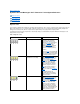
Back to Contents Page System Codes and Messages: Dell™ Dimension™ 2100 System Reference Diagnostic Codes POST Beep Codes System Messages Diagnostic Codes Your computer is equipped with four diagnostic code lights, which are labeled "A," "B," "C," and "D" on the back of the computer. Each of the four lights can be yellow, green, or off, as shown in Table 1. When the computer is turned on or restarted and is functioning normally, the lights flash during power-on self-test (POST).
Microprocessor has failed a BIOS test. If the problem persists, see "Contacting Dell" in the Solutions Guide for instructions on obtaining technical assistance. Memory failed to be sized or enabled. Reseat the memory modules. If the problem persists, remove all but one memory module, and then restart the computer. Repeat this step until the malfunctioning memory module is identified. PCI bus failure has occurred. Remove all cards and restart the computer to determine if a resource conflict exists.
obtaining technical assistance. 7 Processor exception error See "Contacting Dell" in the Solutions Guide for instructions on obtaining technical assistance. 8 Video display memory error See "Contacting Dell" in the Solutions Guide for instructions on obtaining technical assistance. 9 Optional ROM checksum error See "Contacting Dell" in the Solutions Guide for instructions on obtaining technical assistance.
Invalid Boot Diskette The operating system cannot be located on drive A or drive C. KB/Interface Error An error occurred with the keyboard connector. The keyboard or system board may need to be replaced. Keyboard Error nn The BIOS has detected a stuck key represented by scan code nn. Make sure that nothing is resting on the keyboard; if a key appears to be stuck, carefully pry it up. If the problem persists, you may need to replace the keyboard.
Back to Contents Page Resolving Software and Hardware Incompatibilities: Dell™ Dimension™ 2100 System Reference Windows 98 and Windows Millennium Edition (Me) Hardware and Software Incompatibility Occurrences Windows 2000 Hardware and Software Incompatibility Occurrences Windows® 98 and Windows Me Hardware and Software Incompatibility Occurrences Interrupt request (IRQ) conflicts occur on computers running the Microsoft® Windows 98 or Windows Me operating system if a device is either: l Not detected duri
Conflicts are indicated by a yellow exclamation point (!) beside the conflicting device or a red X if the device has been disabled. 7. Double-click any conflicting device listed to bring up the Properties window so you can determine what needs to be reconfigured or removed from the Device Manager. Resolve these conflicts before checking specific devices. 8. Double-click the malfunctioning device type in the Device Manager list. 9. Double-click the icon for the specific device in the expanded list.
Back to Contents Page Controls and Lights: Dell™ Dimension™ 2100 System Reference Front Panel Back Panel Front Panel 1 Floppy-drive access light — Lights up when a floppy drive is being accessed. 2 Power — Turns the computer on and off. Lights up when the computer is on. Press and hold for 4 seconds to shut down. 3 Hard-drive access light — Lights up when a hard drive is being accessed. Back Panel 1 Voltage selection switch — Selects the operating voltage for the computer.
Back to Contents Page Conventions: Dell™ Dimension™ 2100 System Reference Notes, Notices, and Cautions Typographical Conventions The following subsections describe notational conventions used in this document. Notes, Notices, and Cautions Throughout this guide, blocks of text may be accompanied by an icon and printed in bold type or in italic type.
Back to Contents Page Documentation: Dell™ Dimension™ 2100 System Reference Printed Documentation Online Documentation Printed Documentation The following printed documents are provided to you with your purchase of your computer. They are located inside the documentation box that came with your computer. For your convenience, you may also view these documents online. Be sure to read the following instructions thoroughly before viewing the documents.
1. Click the Start button on the Windows desktop, point to Programs, and then click Windows Explorer. 2. Navigate to the directory in which you saved the Tell Me How help file. 3. Double-click the file (tellhow.chm).
Back to Contents Page Drivers: Dell™ Dimension™ 2100 System Reference Your Computer's Drivers Using the Dell Dimension ResourceCD to Reinstall Drivers All of your computer’s drivers for Dell-installed devices are operative when you receive the computer—no further installation or configuration is needed. However, if you ever need to reinstall any of these drivers, the driver files are provided on the Dell Dimension ResourceCD. Device problems can often be corrected by reinstalling the appropriate drivers.
1. Be sure your computer is selected in the System Model list. 2. Be sure your operating system is selected in the Operating System list. 3. Select the type of device in the Device Type list. NOTICE: The Dell Dimension ResourceCD contains drivers for devices that are not part of your computer. Only reinstall the specific drivers for hardware included in your computer. Otherwise, your computer might not work correctly. 4. Select a topic in the Topic list.
Back to Contents Page Removing and Replacing Parts: Dell™ Dimension™ 2100 System Reference Overview Hard Drive Precautionary Measures Power Supply and Fan Assembly Recommended Tools Control Panel Cover Cards Rotating the Power Supply Memory Front panel Heat Sink 3.5-Inch Front Panel Insert Microprocessor Upper 3.5-Inch Drive Battery Lower 3.5-Inch Floppy Drive System Board 5.
l Wide flat-blade screwdriver l #1 and #2 Phillips-head screwdrivers l 1/4-inch nut driver l Tweezers or long-nose pliers l Wrist grounding strap Cover 1 Release latch 2 Computer cover To remove the computer cover, perform the following steps. NOTICE: To avoid inadvertently damaging the system board, be sure you that disconnect the computer from the electrical outlet, disconnect the power cable from the back of the computer, and press the power button before removing the computer cover.
1 Release latch 2 Power supply 3 Drive power cables 1. Remove the computer cover. 2. Lay the computer on its side. 3. Press the release latch while lifting the power supply. 4. Rotate the power supply out of the computer while keeping the drive power cables clear. 5. When you rotate the power supply back into the computer, gently lift the and hold the drive cables out of the way. 6. Rotate the power supply into position until its release latch clicks. Lay the drive power cables along the top of the latch.
1 Front-panel release tab 2 Retaining hooks To remove the front panel: 1. Remove the computer cover. 2. While facing the front of the computer, press in the front-panel release tab the top of the computer. 3. Swing the front panel away from the computer, disengage the two retaining hooks at the bottom of the front panel, and carefully pull it away from the computer. 4. To replace the front panel, fit the two front-panel retaining hooks into their corresponding slots on the computer frame.
1 Drive bay plate To remove the upper 3.5-inch drive plate and install a new drive: 1. Remove the front panel. 2. Remove the 3.5-inch front panel insert. 3. Rotate the power supply away from the system board. While holding the power supply, place the computer in the upright position. 4. Remove the metal plate covering the bay by using a screwdriver to pop out the metal plate from the left or right side of the computer frame. 5. Remove the extra rails from the inside front of the computer frame. 6.
1 Drive-release rail tabs (2) To remove the 5.25-inch drive: 1. Remove the front panel. 2. Rotate the power supply away from the system board. 3. While holding the power supply, place the computer in the upright position. 4. Disconnect the power and interface cables from the back of the drive. 5. Press the two drive-release rail tabs, and slide the drive out of the drive bay. Before you install the new drive, install the drive-release rails on the sides of the replacement drive.
3. Secure the drive to the front of the computer frame with the two screws you removed. 4. Connect a power supply cable and the hard drive interface cable to the new drive. Power Supply and Fan Assembly 1 Power-supply retaining clips 2 Power supply and fan assembly To remove the power supply and fan assembly: 1. Disconnect the AC power cable from the computer. 2. Remove the computer cover. 3. Rotate the power supply away from the system board. 4.
1 Card connector 2 Card 3 System-board card connector 4 Card mounting bracket and screw To install a card: 1. Remove the computer cover. 2. Rotate the power supply. 3. Choose a system-board card connector for the card. 4. Unscrew and remove the metal filler bracket that covers the card-slot opening for the card slot you intend to use. 5. Insert the card firmly into the system-board card connector. Align the cutout on the bottom of the card connector with the crossbar in the system-board card connector.
2. Rotate the power supply. 3. If necessary, remove a memory module: a. Press out the securing clip at each end of the memory connector. b. Grasp the module and pull up. c. If the module is difficult to remove, gently ease the module back and forth to remove it from the connector. 4. To insert a module, press out the securing clip at each end of the memory connector. 5. Align the notches on the bottom of the module with the crossbars in the connector.
d. Connect the fan to the system board. 10. Replace the computer cover, and then reconnect your computer and peripherals to their electrical outlets and turn them on. As the computer boots, it detects the presence of the new microprocessor and automatically changes the system configuration information in the system setup program. 11. Enter the system setup program, and confirm that the Processor Type and Processor Speed options correctly identify the newly installed microprocessor.
microprocessor socket, you do not need to use force, which could bend the pins if the chip is misaligned. When the chip is positioned correctly, press it with minimal pressure to seat the microprocessor in the socket. Be careful not to bend the pins. d. When the chip is fully seated in the socket, pivot the microprocessor-socket release lever back toward the socket until it snaps into place, securing the chip.
1 System-board retaining clip 2 System board 3 Standoffs 1. If possible, enter the system setup program and print the system setup screens by pressing the key before you turn off the computer because you will have to restore the configuration information after the system board is replaced. 2. Remove the computer cover. 3. Remove the power supply. 4. Disconnect any cables connected to cards, and remove these cards. 5. Disconnect all internal cables from the system board. 6.
7. Re-enter the system setup program, and reset the system configuration information.
Back to Contents Page Technical Specifications: Dell™ Dimension™ 2100 System Reference Microprocessor Power System Information Physical Expansion Bus Environmental Memory Regulatory Notices Drives IRQ Assignments Ports Default Dell-Installed Card Placement Video Microprocessor Microprocessor type Intel® Pentium® III processor 933 MHz or 1.00 GHz internally and 133 MHz externally or 1.10 GHz internally and 100 MHz externally NOTE: Microprocessor offerings vary by country.
Architecture non-ECC SDRAM 168-pin modules Memory sockets two; gold contacts Memory capacities 64, 128, 256, and 512 MB Minimum memory1 64 MB for Microsoft® Windows® 98, Windows Millennium Edition (Me), and Windows 2000; 128 MB for Windows XP Maximum memory1 512 MB Frequency 100 MHz NOTE: Your computer may have either PC 100 or shared2 PC 133-SDRAM modules at 100 MHz installed. Do not mix these two module types in the computer.
Video controller Intel 810e chip set with Dynamic Video Memory and 4-MB, 133-MHz display cache or Intel 810 chip set with Dynamic Video Memory Power DC power supply Wattage 145 W Heat dissipation 700 BTU (fully loaded system without monitor) Voltage (switch selectable on back panel) 90 to 135 V at 60 Hz; 180 to 265 V at 50 Hz; 100 V at 50 to 60 Hz for Japanese systems Backup battery 3-V CR2032 coin cell Physical Height 39 cm (15.375 inches) Width 16.8 cm (6.625 inches) Depth 34 cm (13.
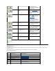
IRQ Assignments IRQ Line System Resource IRQ Line System Resource IRQ0 System timer IRQ8 RTC IRQ1 Keyboard buffer IRQ9 Available IRQ2 Enables IRQ8 through IRQ15 IRQ10 Available IRQ3 Available4 IRQ11 Available IRQ4 Serial port IRQ12 Mouse port IRQ5 Available IRQ13 Math coprocessor IRQ6 Floppy/tape drive controller IRQ14 Primary IDE channel IRQ7 Parallel port IRQ15 Secondary IDE channel 4 IRQ3 is available provided that no other device in the computer (such as a modem) is u
Back to Contents Page System Setup Program: Dell™ Dimension™ 2100 System Reference Overview Security Screen Entering the System Setup Program Boot Screen Main Screen Exit Screen Advanced Screen Clearing NVRAM Overview Each time you turn on or restart your computer, it compares the hardware installed in the computer to the hardware listed in the configuration information stored in nonvolatile random-access memory (NVRAM) on the system board.
Table 1. Main Screen Menu Options Option Function BIOS Version Displays the version of the BIOS being used. Processor Type Displays the type of microprocessor installed. Processor Speed Displays the internal speed of the microprocessor. Cache RAM Displays the cache random access memory. Service Tag Displays the service tag for the computer. Total Memory Displays the total computer memory. Memory Bank 0 Displays the memory installed in memory bank 0.
IDE Configuration Displays the IDE Configuration submenu. Diskette Configuration Displays the Diskette Configuration submenu. Event Log Configuration Displays the Event Log Configuration submenu. Video Configuration Displays the Video Configuration submenu. Boot Configuration Submenu Table 3. Boot Configuration Submenu Options Option Function Plug and Play OS Determines whether the computer is configured to support Plug and Play devices from the operating system or from the system BIOS.
Base I/O Address If port is set to Enabled, available I/O addresses are 3F8, 3E8, 2F8, and 2E8. Interrupt Parallel port If port is set to Enabled, available interrupts are IRQ3 and IRQ4. Configures the parallel port. Set this option to Auto (default), Enabled, or Disabled. Depending on the port setting, you can set the following additional options: Mode If port is set to Auto or Enabled, available modes are Output Only, Bi-directional, ECP (default), and EPP.
Table 6. Primary IDE Master Submenu Options Option Function Type Specifies the type of hard drive. Settings for this option are User, Auto, CD-ROM, ATAPI Removable, Other ATAPI, IDE Removable, and None. LBA Mode Control Determines LBA mode control. Set to Enabled (default) unless directed to change it by a Dell technical support representative. Multi-Sector Transfers Determines the number of sectors per block during multiple-sector transfers.
Table 8. Event Log Configuration Submenu Options Option Function Event Log Displays the space available for the event log. Event Log Validity Displays the validity of the event log. View Event Log Press to view the event log. Clear All Event Logs Clears all event logs when the computer restarts if set to Yes. Retains the event log information if set to No (default). Event Logging Enables or disables event logging.
Table 10. Security Screen Options Option Function Supervisor Password Is Indicates whether a supervisor password has been assigned. User Password Is Indicates whether a user password has been assigned. Set Supervisor Password Sets and confirms a supervisor password. Set User Password Sets and confirms a user password. Clear User Password Clears the user password. Settings for this option are Yes or No (default). Boot Screen Table 11.
this option are Power On or Stays Off (default). 1st Boot Device Determines which device the computer tries to boot from first. Use the up- or down-arrow key to highlight a device. Settings for this option are as follows: l Floppy l ARMD FDD l ARMD HDD l IDE-HDD l ATAPI CD-ROM l SCSI* l Network* l Disabled *Where SCSI or Network is the name of the installed device.
Clearing NVRAM To clear NVRAM for all devices and restart the computer: 1. Enter the system setup program. 2. Press the right-arrow key to move to the Advanced menu. 3. Press the down-arrow key to highlight the Boot Configuration submenu, and press . 4. Press the down-arrow key to highlight Reset Config Data. Then change the setting to Yes (see Table 3). 5. Press to exit the program and restart the computer.
Back to Contents Page Technical Overview: Dell™ Dimension™ 2100 System Reference Internal View Power Supply Back-Panel Features DC Power Cables System Board Connectors and Sockets DC Power Connector Pin Assignments System Board Configuration Jumper Control Panel Connector (J9F2) Pin Assignments Internal View 1 Front-panel release 2 5.25-inch drive bay 3 3.
1 Microprocessor connector (J5H1) 12 Speaker (LS9A1) 2 Memory sockets (BANKn) 13 Configuration jumper (J7A1) 3 Fan connector (J3J1) 14 Power light 4 3.
The 145-watt (W) power supply can operate from an AC power source of 115 volts AC (VAC) at 60 hertz (Hz) or 230 VAC at 50 Hz. The power supply provides the DC operating voltages and currents listed in the following table. NOTE: The power supply produces DC voltages only under its loaded condition. The DC power cable connectors must be connected to their corresponding power input connectors on the system board or drives to measure these voltages. DC Voltage Ranges Maximum Output Current Voltage Range +3.
2 Common (black) 12 Common (black) 3 +5 VDC (red) 13 Common (black) 4 Common (black) 14 Common (black) 5 15 –5 VDC (white) PWRGOOD1 (orange) 6 +5 VFP (purple) 16 +5 VDC (red) 7 +12 VDC (yellow) 17 +5 VDC (red) 8 –12 VDC (blue) 18 +5 VDC (red) 9 Common (black) 19 Not connected 10 Common (black) 20 +5 VDC (red) 1 Pin 5 — PWRGOOD is a status signal generated by the power supply to notify the computer that the DC operating voltages are within the ranges required for proper computer operation
Back to Contents Page