
User's Manual
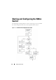
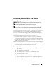
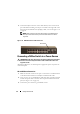
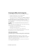
Table Of Contents
- Getting Started Guide
- Guide de mise en route
- Introduction
- Présentation de la série N20xx
- Présentation du matériel de la série N20xx
- Installation de la série N20xx
- Démarrage et configuration du commutateur N20xx
- Présentation de la série N30xx
- Présentation du matériel de la série N30xx
- Installation de la série N30xx
- Démarrage et configuration du commutateur N30xx
- Handbuch zum Einstieg
- Einführung
- Übersicht über die Reihe N20xx
- Übersicht über die Hardware der Reihe N20xx
- Installation von Modellen der Reihe N20xx
- Starten und Konfigurieren eines Switches der Reihe N20xx
- Übersicht über die Reihe N30xx
- Übersicht über die Hardware der Reihe N30xx
- Installation von Modellen der Reihe N30xx
- Starten und Konfigurieren eines Switches der Reihe N30xx
- Руководство по началу работы
- Содержание
- Введение
- Обзор серии N20xx
- Обзор аппаратного обеспечения серии N20xx
- Установка серии N20xx
- Запуск и конфигурация коммутатора серии N20xx
- Обзор серии N30xx
- Обзор аппаратного обеспечения серии N30xx
- Установка серии N30xx
- Запуск и конфигурация коммутатора серии N30xx
- Guía de introducción
- Introducción
- Información general sobre la serie N20xx
- Información general sobre el hardware de la serie N20xx
- Instalación de la serie N20xx
- Inicio y configuración del conmutador N20xx
- Información general sobre la serie N30xx
- Información general sobre el hardware de la serie N30xx
- Instalación de la serie N30xx
- Inicio y configuración del conmutador N30xx
- Başlangıç Kılavuzu
- Içerik
- Giri
- N20xx Serisine Genel Bakış Genel Bakış
- N20xx Serisinin Donanımına Genel Bakış
- N20xx Serisinin Kurulumu
- N20xx Anahtarın Başlatılması ve Yapılandırılması
- N30xx Serisine Genel Bakış
- N30xx Serisinin Donanımına Genel Bakış
- N30xx Serisinin Kurulumu
- N30xx Anahtarın Başlatılması ve Yapılandırılması
- מדריך תחילת העבודה
22 Getting Started Guide
3
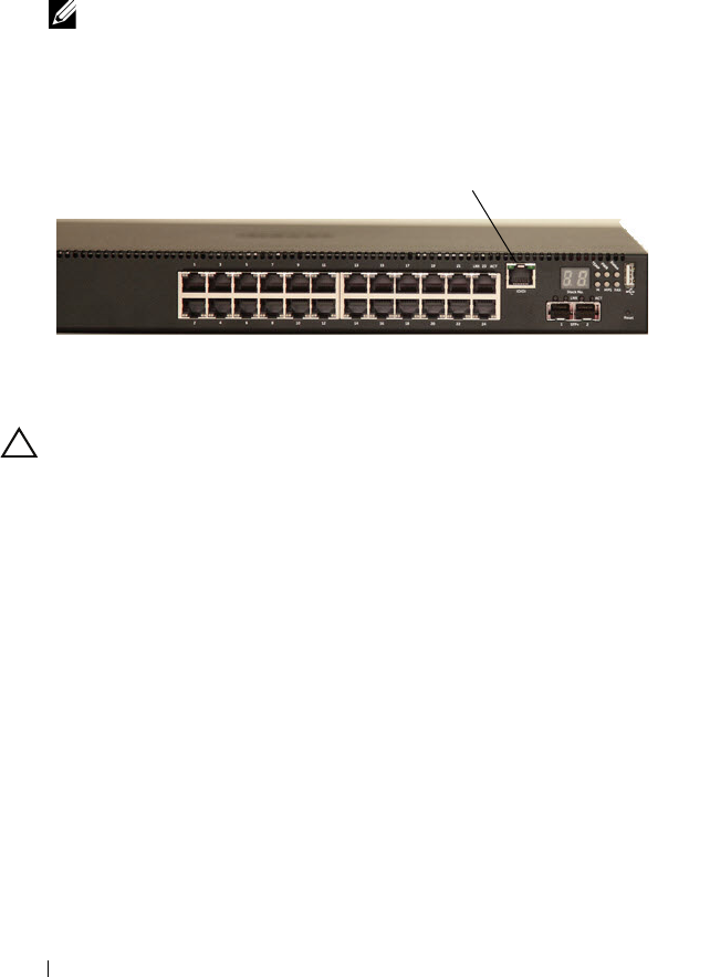
Connect the RJ-45 connector on the cable directly to the switch console
port. The Dell Networking console port is located on the right side of the
front panel and is labeled with a
|O|O|
symbol, as shown in Figure 1-10
on page 22.
NOTE: Serial console access to the stack manager is available from any
serial port via the local CLI. Only one serial console session at a time is
supported.
Figure 1-10. N2024P Front Panel with Console Port
Connecting a N20xx Switch to a Power Source
CAUTION: Read the safety information in the Safety and Regulatory Information
manual as well as the safety information for other switches that connect to or
support the switch.
All N20xx models have one internal power supply. The
power receptacles are
on the back panel.
AC and DC Power Connection
1
Make sure that the switch console port is connected to a VT100 terminal
or VT100 terminal emulator via the RJ-45 to DB-9 female cable.
2
Using a 5-foot (1.5 m) standard power cable with safety ground connected,
connect the power cable to the AC main receptacle located on the back
panel (see Figure 1-11 on page 23).
3
Connect the power cable to a grounded AC outlet.
Console Port