Appendix A: Configuration Examples This Appendix provides some configuration examples for the PowerConnect 2708/2716/2724 devices installed in the Enterprise Network.
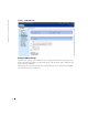
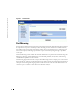
www.dell.com | support.dell.com Configuring Interface Parameters The Interface Configuration screen enables the user to set the various interface parameters, interface type and additional operational attributes. In the following example, Port 1 is configured as 1000Mbps Copper interface type, as maximum speed and interface media type. The appropriate cable type connection is RJ-45 1 Gigabit connection. The Admin Status is Enabled, therefore traffic is forwarded through the port.
Figure 9-2. Port-Based VLANs in the Enterprise Creating VLAN Membership VLANs are collections of switching ports that comprise a single broadcast domain. Packets are classified as belonging to a VLAN based on either the VLAN tag, or a combination of the ingress port and packet contents. Packets sharing common attributes can be grouped in the same VLAN. VLAN tagging provides a method of transferring VLAN information between VLAN groups. VLAN tagging attaches a 4-byte tag to packet headers.
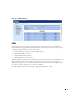
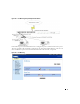
www.dell.com | support.dell.com Figure 9-3. VLAN Membership Defining VLAN Port Settings The VLAN Port Settings screen enables the user to configure information for a specific port in a LAG. In the following example, port #2 in LAG Group 1, has the Frame Type as Admit All, and Ingress Filtering is Disabled. The follwing screen shows the specific status information relevant to a specific port, and global status information relevant to all ports.
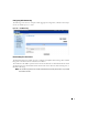
Figure 9-4. VLAN Port Settings LAGs A Link Aggregated Group (LAG) is composed of ports with the same speed, set to full-duplex operation. Up to six Aggregated Links may be defined, each with up to four member ports, to form a single Link Aggregated Group (LAG).
www.dell.com | support.dell.com Figure 9-5. LAGs in the PowerConnect Departmental Switch Aggregating Ports Link Aggregation optimizes port usage by linking a group of ports together to form a single LAG (aggregated group). Aggregating ports multiplies the bandwidth between the devices, increases port flexibility, and provides link redundancy. Consider the following when aggregating ports: • Link Aggregation is allowed between two devices only. • All ports within a LAG must be the same media type.
Configuring LAG Membership The following screen shows an example of Link Aggregation configuration, whereby LAG Group 4 consists of member ports 5, 6, and 7. Figure 9-6. LAG Membership Downloading Files from Server The File Download screen enables the user to configure and update Software Image files or BootP Image files in the PowerConnect 2708/2716/2724 devices. The TFTP Server IP Address specifies the location from which files are donloaded. The File Name specifies the file to be downloaded.
www.dell.com | support.dell.com Figure 9-7. File Download Port Mirroring PowerConnect 2708/2716/2724 support port mirroring functionality. Port Mirroring allows traffic to be copied from one port to another port. Port mirroring monitors and mirrors network traffic by forwarding copies of incoming and outgoing packets from a monitored port to a monitoring port. The user can specify which target port receives copies of all traffic passing through a specified source port.
Figure 9-8. Port Mirroring Setup with Departmental Switch In the following screen, the Destination Port is configured as port 3, and the Source Port as port 7. The type of traffic to be monitored is configured as Tx (Transmit) and Rx (Receive). The user can elect to add/remove ports to be mirrored and monitored on the network, as required. Figure 9-9.
www.dell.com | support.dell.com Storm Control Enabling Storm Control The Storm Control mechanism is useful when a faulty Network Interface Card (NIC), or Broadcast or Multicast frames cause network flooding, beyond the threshold rate limit. When Layer 2 frames are forwarded, Broadcast and Multicast frames cause flooding to all ports on the relevant VLAN. This occupies bandwidth, and loads all nodes connected on all ports.
Configuring Class of Service (CoS) The underlying mechanism of Class of Service (CoS) is the concept of queues. After packets are assigned to a specific egress queue, CoS services can be assigned to the queue(s). The PowerConnect 2708/2716/2724 system supports four queues per port for service priorities, where queue 0 is the lowest priority and queue 3 is the highest priority. For each logical group of priorities defined by the user, two priority levels are defined.
www.dell.com | support.dell.com The common prioritization mechanisms implemented in the PowerConnect device are Class of Service (CoS), according to IEEE802.1p, and DSCP (DiffServe Code Point) for IP traffic. CoS reduces flow complexity by mapping multiple flows into eight classes of service. These classes are set in the VPT (VLAN Priority Tag) 4-byte field tag, added to the packet by either a station or networking device.
When Restore Defaults box is checked, the device’s factory default settings for mapping CoS values are restored. Figure 9-13. CoS to Queue Mapping DSCP Values to Queues The following screen shows DSCP In incoming traffic and the priority queues (1 to 4) assigned to them. Figure 9-14.
www.dell.com | support.dell.