
Getting Started Guide


Getting Started With Your System
7
Operating the PowerConnect RPS720 After Installation
1
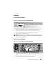
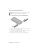
Plug one end of the switch DC power cord (14-pin) into the connector
labeled
RPS
on the back of the switch. Connect the other end of the
switch DC power cord to any available RPS connector on the back of
the
PowerConnect
RPS720.
Figure 1-5. Back View–PowerConnect RPS720
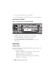
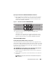
2
Attach the AC power cord to the
PowerConnect
RPS720 and to
an AC power outlet.
The switch is now using both power supplies simultaneously. You can
monitor the status of the two power supplies through the front panel
LEDs on your PowerConnect switch and the
PowerConnect
RPS720.
PowerConnect MPS600 or MPS1000
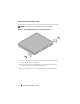
Installing PowerConnect MPS600 or MPS1000 on a Flat Surface
You can install the PowerConnect MPS600 or MPS1000 on any appropriate
level surface that can safely support the weight of the switch,
the PowerConnect MPS600 or MPS1000, and their attached cables.
There must be adequate space around the PowerConnect MPS600 or
MPS1000 for ventilation and to access cable connectors.
CAUTION:
Allow at least 2 inches (5.1 cm) on each side for proper ventilation and
5 inches (12.7 cm) at the back for power cord clearance.
1
Set the
PowerConnect
MPS600 or MPS1000 on the flat surface and check
for proper ventilation.
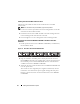
2
Attach rubber feet (optional) on each marked location at the bottom of
the chassis.
NOTE:
Although optional, rubber feet are recommended to keep the unit
from slipping.