53-1002449-01 15 December 2011 Brocade 6505 Hardware Reference Manual ®
Copyright © 2011 Brocade Communications Systems, Inc. All Rights Reserved. Brocade, the B-wing symbol, BigIron, DCX, Fabric OS, FastIron, NetIron, SAN Health, ServerIron, and TurboIron are registered trademarks, and Brocade Assurance, Brocade NET Health, Brocade One, CloudPlex, MLX, VCS, VDX, and When the Mission Is Critical, the Network Is Brocade are trademarks of Brocade Communications Systems, Inc., in the United States and/or in other countries.
Contents About This Document In this chapter . . . . . . . . . . . . . . . . . . . . . . . . . . . . . . . . . . . . . . . . . . . vii How this document is organized . . . . . . . . . . . . . . . . . . . . . . . . . . . . vii Supported hardware and software . . . . . . . . . . . . . . . . . . . . . . . . . . vii Document conventions . . . . . . . . . . . . . . . . . . . . . . . . . . . . . . . . . . . . viii Text formatting . . . . . . . . . . . . . . . . . . . . . . . . . . . . . . . . . . . . . . .
Brocade 6505 configuration . . . . . . . . . . . . . . . . . . . . . . . . . . . . . . . . 8 Providing power to the switch . . . . . . . . . . . . . . . . . . . . . . . . . . . . 8 Creating a serial connection . . . . . . . . . . . . . . . . . . . . . . . . . . . . . 8 Switch IP address. . . . . . . . . . . . . . . . . . . . . . . . . . . . . . . . . . . . . . 9 Date and time settings . . . . . . . . . . . . . . . . . . . . . . . . . . . . . . . . 10 Brocade Inter-Switch Link Trunking . . . . . . . . . . .
Data transmission ranges . . . . . . . . . . . . . . . . . . . . . . . . . . . . . . . . . 35 Memory specifications . . . . . . . . . . . . . . . . . . . . . . . . . . . . . . . . . . . . 36 Fibre Channel port specifications . . . . . . . . . . . . . . . . . . . . . . . . . . . 36 Serial port specifications . . . . . . . . . . . . . . . . . . . . . . . . . . . . . . . . . . 36 Access Gateway default port mapping . . . . . . . . . . . . . . . . . . . . . . . 37 Regulatory compliance . . . . . . . . . . . . .
vi Brocade 6505 Hardware Reference Manual 53-1002449-01
About This Document In this chapter • How this document is organized . . . . . . . . . . . . . . . . . . . . . . . . . . . . . . . . . . vii • Supported hardware and software. . . . . . . . . . . . . . . . . . . . . . . . . . . . . . . . . vii • Document conventions . . . . . . . . . . . . . . . . . . . . . . . . . . . . . . . . . . . . . . . . . . viii • Notice to the reader . . . . . . . . . . . . . . . . . . . . . . . . . . . . . . . . . . . . . . . . . . . . . ix • Additional information . . . . . . .
Document conventions This section describes text formatting conventions and important notice formats used in this document.
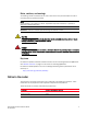
Notes, cautions, and warnings The following notices and statements are used in this manual. They are listed below in order of increasing severity of potential hazards. NOTE A note provides a tip, guidance, or advice, emphasizes important information, or provides a reference to related information. ATTENTION An Attention statement indicates potential damage to hardware or data.
Corporation Referenced trademarks and products Red Hat, Inc. Red Hat, Red Hat Network, Maximum RPM, Linux Undercover Velcro Industries B.V. Velcro Additional information This section lists additional Brocade and industry-specific documentation that you might find helpful. Brocade resources To get up-to-the-minute information, go to http://my.brocade.com to register at no cost for a user ID and password.
• supportSave command output • Detailed description of the problem, including the switch or fabric behavior immediately following the problem, and specific questions • Description of any troubleshooting steps already performed and the results • Serial console and Telnet session logs • syslog message logs 2.
xii Brocade 6505 Hardware Reference Manual 53-1002449-01
Chapter Brocade 6505 Introduction 1 In this chapter • Brocade 6505 overview . . . . . . . . . . . . . . . . . . . . . . . . . . . . . . . . . . . . . . . . . . 1 • Port side of the Brocade 6505 . . . . . . . . . . . . . . . . . . . . . . . . . . . . . . . . . . . . . 3 • Nonport side of the Brocade 6505 . . . . . . . . . . . . . . . . . . . . . . . . . . . . . . . . .
1 Brocade 6505 overview • Universal ports self-configure as E, F, or M ports. EX_Ports can be activated on a per-port basis with the optional Integrated Routing license. D-port functionality is also available for diagnostics. • Airflow is set for port side exhaust.
Port side of the Brocade 6505 1 • An RJ45 10/100 BaseT Ethernet system management port, in conjunction with Brocade EZSwitchSetup, that supports switch IP address discovery and configuration, eliminating the need to attach a serial cable to configure the switch IP address and greatly increasing the ease of use. • One RS-232 serial port with an RJ45 connector for initial switch setup (if not using EZSwitchSetup) and factory default restoration. • A USB 2.
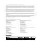
1 Nonport side of the Brocade 6505 1 2 3 4 5 6 7 8 1 System status LED 5 System power LED 2 Management Ethernet port with LEDs 6 Serial console port 3 USB port 7 Switch ID pull-out tab 4 FC ports 0-3 (all LEDs above) 8 FC ports 4-7 FIGURE 1 Port side of the Brocade 6505 NOTE The two LEDs on the serial console port are non-functional.
Chapter Brocade 6505 Installation and Configuration 2 In this chapter • Items included with the Brocade 6505 . . . . . . . . . . . . . . . . . . . . . . . . . . . . . . 5 • Installation and safety considerations . . . . . . . . . . . . . . . . . . . . . . . . . . . . . . . 5 • Standalone installation for a Brocade 6505 . . . . . . . . . . . . . . . . . . . . . . . . . . 7 • Cabinet installation for a Brocade 6505 . . . . . . . . . . . . . . . . . . . . . . . . . . . . . 8 • Brocade 6505 configuration. .
2 Installation and safety considerations Electrical considerations To install and operate the switch successfully, ensure the following: • The primary outlet is correctly wired, protected by a circuit breaker, and grounded in accordance with local electrical codes. • The supply circuit, line fusing, and wire size are adequate, as specified by the electrical rating on the switch nameplate. • The power supply standards provided in Table 7, “System power specifications” are met.
Standalone installation for a Brocade 6505 2 Cables can be organized and managed in a variety of ways, for example, using cable channels on the sides of the cabinet or patch panels to minimize cable management. Following is a list of recommendations: NOTE You should not use tie wraps with optical cables because they are easily overtightened and can damage the optic fibers. • Plan for rack space required for cable management before installing the switch. • Leave at least 1 m (3.
2 Cabinet installation for a Brocade 6505 4. Provide power to the switch as described in “Providing power to the switch” on page 8. ATTENTION Do not connect the switch to the network until the IP address is correctly set. For instructions on how to set the IP address, see “Brocade 6505 configuration.
Brocade 6505 configuration 2 Complete the following steps to create a serial connection to the switch. 1. Connect the serial cable to the serial port on the switch and to an RS-232 serial port on the workstation. If the serial port on the workstation is RJ45 instead of RS-232, remove the adapter on the end of the serial cable and insert the exposed RJ45 connector into the RJ45 serial port on the workstation. 2.
2 Brocade 6505 configuration If you are going to use an IPv6 address, enter the network information in semicolon-separated notation as a standalone command. switch:admin> ipaddrset -ipv6 --add 1080::8:800:200C:417A/64 IP address is being changed...Done. Date and time settings The Brocade 6505 maintains the current date and time inside a battery-backed real-time clock (RTC) circuit. Date and time are used for timestamping log events.
Brocade 6505 configuration 2 All switches in the fabric maintain the current clock server IP address in non-volatile memory. By default, this value is LOCL, the local clock server of the Principal (when FCS not enabled) or Primary (when FCS is enabled) switch. Changes to the clock server value on the Principal or Primary switch are propagated to all switches in the fabric.
2 Brocade 6505 configuration 1. Log in to the switch using the default password (which is password). 2. Enter the tsTimeZone command as follows: Use timezonename to set the time zone by time zone ID, such as PST or Country/City. The following example shows how to change the time zone to US/Central. The tsTimeZone command by itself display the current time zone.
Fabric OS Native and Access Gateway modes 2 Changes to the clock server value on the principal or primary FCS switch are propagated to all switches in the fabric. Brocade Inter-Switch Link Trunking Brocade Inter-Switch Link (ISL) Trunking is optional software that allows you to create trunking groups of ISLs between adjacent switches.
2 Fabric OS Native and Access Gateway modes • Access Gateway simplifies SAN deployment by using N_Port ID Virtualization (NPIV). NPIV provides Fibre Channel switch functions that improve switch scalability, manageability, and interoperability. For more information on Access Gateway, refer to the following: - For a list of F_Ports mapped to N_Ports by default, refer to “Access Gateway default port mapping” on page 37.
Fabric OS Native and Access Gateway modes 2 • Ensure that no zoning or Admin Domain (AD) transaction buffers are active. If any transaction buffer is active, enabling Access Gateway mode will fail with the error, “Failed to clear Zoning/Admin Domain configuration.” Use the following steps to enable Access Gateway mode using Fabric OS commands. 1.
2 16 Fabric OS Native and Access Gateway modes Brocade 6505 Hardware Reference Manual 53-1002449-01
Chapter 3 Brocade 6505 Operation In this chapter • Powering the Brocade 6505 on and off. . . . . . . . . . . . . . . . . . . . . . . . . . . . . • LED activity interpretation. . . . . . . . . . . . . . . . . . . . . . . . . . . . . . . . . . . . . . . . • POST and boot specifications . . . . . . . . . . . . . . . . . . . . . . . . . . . . . . . . . . . . . • Interpreting POST results . . . . . . . . . . . . . . . . . . . . . . . . . . . . . . . . . . . . . . . . • Brocade 6505 maintenance. . . . . . . .
3 LED activity interpretation LED activity interpretation System activity and status can be determined through the activity of the LEDs on the switch. There are three possible LED states: no light, a steady light, and a flashing light. Flashing LEDs may be slow, fast, or flickering. The LED colors are either green or amber. Sometimes, the LEDs flash either of the colors during boot, POST, or other diagnostic tests.
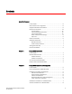
LED activity interpretation 1 2 3 4 5 7 6 8 1 System power LED (green) 5 FC port status LED (port 0) 2 System status LED green/amber) 6 FC port status LED (port 4) 3 Ethernet port activity LED (amber) 7 FC port 0 4 Ethernet port speed LED (green) 8 FC port 4 FIGURE 3 3 LEDs on the port side of Brocade 6505 NOTE The two LEDs on the serial console port are non-functional.
3 LED activity interpretation Figure 4 shows the LEDs on the nonport side of the switch. 1 1 Power supply and fan assembly #1 status LED FIGURE 4 LEDs on the nonport side of Brocade 6505 LED patterns Table 1 describes the port side LEDs and their behavior. TABLE 1 Port side LED patterns during normal operation LED name LED color Status of hardware Recommended action Power Status (green) No light System is off or there is an internal power supply failure.
POST and boot specifications TABLE 1 3 Port side LED patterns during normal operation (Continued) LED name LED color Status of hardware Recommended action Optical media port status (one bicolor LED for each FC port) Off No light or signal carrier on the media interface. Verify that the transceiver is installed correctly and that the cable is connected correctly. Steady amber Receiving light or carrier, but not online. No action required.
3 Interpreting POST results POST The success or failure results of the diagnostic tests that run during POST can be monitored through LED activity, the error log, or the command line interface. POST includes the following tasks: • Conducts preliminary POST diagnostics. • Initializes the operating system. • Initializes hardware. • Runs diagnostic tests on several functions, including circuitry, port functionality, memory, statistics counters, and serialization.
Brocade 6505 maintenance 3 For information about all referenced commands, and on accessing the error log, refer to the Fabric OS Administrator’s Guide. For information about error messages, refer to the Fabric OS Message Reference Manual. Brocade 6505 maintenance The Brocade 6505 is designed for high availability and low failure; it does not require any regular physical maintenance.
3 Brocade 6505 maintenance ! FIGURE 5 Installing a 16 Gbps SFP+ optical transceiver in the upper row port slot FIGURE 6 Installing an 8 Gbps SFP+ optical transceiver in the upper row port slot Diagnostic tests In addition to POST, Fabric OS includes diagnostic tests to help you troubleshoot the hardware and firmware. This includes tests of internal connections and circuitry, fixed media, and the transceivers and cables in use.
Brocade 6505 management 3 The tests are implemented by command, either through a Telnet session or through a console set up to the serial connection to the switch. Some tests require the ports to be connected by external cables, to allow diagnostics to verify the serializer/deserializer interface, transceiver, and cable. Some tests require loopback plugs. Diagnostic tests run at link speeds of 2, 4, 8, or 16 Gbps depending on the speed of the link being tested and the type of port.
3 26 Brocade 6505 management Brocade 6505 Hardware Reference Manual 53-1002449-01
Chapter Removal and Replacement of Power Supplies and Fans 4 In this chapter • Introduction . . . . . . . . . . . . . . . . . . . . . . . . . . . . . . . . . . . . . . . . . . . . . . . . . . . 27 • Removing and replacing a power supply and fan assembly. . . . . . . . . . . . . 27 Introduction NOTE Read the “Installation and safety considerations” on page 5 before servicing. The field-replaceable units (FRUs) in the Brocade 6505 can be removed and replaced without special tools.
4 Removing and replacing a power supply and fan assembly 1 2 3 4 5 6 7 1 Filler panel 5 Power plug receptacle (with plug retainer) 2 Power supply and fan assembly 1 6 Thumbscrew 3 Power supply and fan assembly LED 7 Handle 4 On/off switch FIGURE 7 Nonport side of the Brocade 6505 CAUTION Disassembling any part of the power supply voids the part warranty and regulatory certifications. There are no user-serviceable parts inside the power supply and fan assembly.
Removing and replacing a power supply and fan assembly TABLE 4 4 Power supply and fan assembly status LED behavior, description, and required actions LED color Description Action required No light Power supply and fan assembly is not receiving power, or is off. Verify that the power supply and fan assembly is on and seated and the power cord is connected to a functioning power source. Steady green Power supply and fan assembly is operating normally. No action is required.
4 Removing and replacing a power supply and fan assembly POWER SUPPLY Unit: 1 Power Source: Time Awake: AC 0 days Power Supply #1 is OK Power Supply #2 is absent br6505:admin> Time required Replacing a power supply and fan assembly in the Brocade 6505 should require less than two minutes to complete.
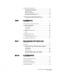
Removing and replacing a power supply and fan assembly 4 1 3 2 4 1 Brocade 6505 chassis 3 Captive screw 2 Power supply and fan assembly 4 Product labels FIGURE 8 Inserting the power supply and fan assembly into the switch Replacing a power supply and fan assembly Refer to Figure 8 for this procedure. Complete the following steps to replace a combined power supply and fan assembly in a Brocade 6505.
4 Removing and replacing a power supply and fan assembly 3. Gently push the power supply and fan assembly into the chassis until it is firmly seated. 4. Using the Phillips screwdriver, secure the power supply and fan assembly to the chassis by tightening in the captive screw. 5. Plug the power cord into the power supply and fan assembly and power on the unit by switching the AC power switch to the I symbol. 6.
Appendix A Brocade 6505 Specifications In this appendix • Weight and physical dimensions . . . . . . . . . . . . . . . . . . . . . . . . . . . . . . . . . . • Facility requirements . . . . . . . . . . . . . . . . . . . . . . . . . . . . . . . . . . . . . . . . . . . . • System power specifications . . . . . . . . . . . . . . . . . . . . . . . . . . . . . . . . . . . . . • Environmental requirements . . . . . . . . . . . . . . . . . . . . . . . . . . . . . . . . . . . . . • General specifications. . . . .
A System power specifications TABLE 6 . Facility requirements Type Requirements Electrical • Adequate supply circuit, line fusing, and wire size, as specified by the electrical rating on the switch nameplate. • Circuit protected by a circuit breaker and grounded in accordance with local electrical codes. Refer to Table 7 on page 34 for complete power supply specifications. Thermal • Cabinet (when rack-mounted) • • • • • A minimum airflow of 79.8 cubic meters/hour (47 cubic ft/min.
General specifications TABLE 8 A Environmental requirements (Continued) Condition Acceptable during operation Acceptable during nonoperation Altitude 0 to 3 km (9,842 feet) above sea level 0 to 12 km (39,370 feet) above sea level Shock 20 G, 6 ms, half-sine wave 33 G, 11 ms, half-sine wave, 3/eg Axis Vibration 0.5 G sine, 0.4 gms random, 5-500 Hz 2.0 G sine, 1.1 gms random, 5-500 Hz Airflow Maximum - 71.36 cmh (42 cfm)??? Nominal - 59.47 cmh (35 cfm)??? NOTE: Airflow is port side exhaust.
A Memory specifications TABLE 10 Supported optics, speeds, cables, and distances (Continued) Transceiver type Form factor Speed Multimode media (62.5 microns) (OM1) Multimode media (50 microns) (OM2) Multimode media (50 microns) (OM3) Multimode media (50 microns) (OM4) Single mode media (9 microns) LWL SFP+ 4 Gbps N/A N/A N/A N/A 30 km (18.6 mi.) SFP+ 8 Gbps N/A N/A N/A N/A 10 km (6.2 mi.) or 40 km (24.8 mi.) SFP+ 16 Gbps N/A N/A N/A N/A 10 km (6.2 mi.
Access Gateway default port mapping A The serial port can be used to connect to a workstation to configure the switch IP address before connecting the switch to a fabric or IP network. The serial port’s parameters are fixed at 9600 baud, 8 data bits, and no parity, with flow control set to None. Table 12 lists the serial cable pinouts.
A Regulatory compliance • “Canadian requirements” on page 40 • “Laser compliance” on page 40 FCC warning (US only) This equipment has been tested and complies with the limits for a Class A computing device pursuant to Part 15 of the FCC Rules. These limits are designed to provide reasonable protection against harmful interference when the equipment is operated in a commercial environment.
Regulatory compliance A Power cords (Japan DENAN) Chinese statement This is a class A product. In a domestic environment this product may cause radio interference in which case the user may be required to take adequate measures. BSMI statement (Taiwan) Warning: This is Class A product. In a domestic environment, this product may cause radio interference, in which case the user may be required to take adequate measures. CE statement ATTENTION This is a Class A product.
A Electrical cautions The standards compliance label on the Brocade 6505 contains the CE mark which indicates that this system conforms to the provisions of the following European Council directives, laws, and standards: • • • • • Electromagnetic Compatibility (EMC) Directive 2004/108/EEC Low Voltage Directive (LVD) 2006/95/EC EN50082-2/EN55024:1998 (European Immunity Requirements) EN61000-3-2/JEIDA (European and Japanese Harmonics Spec) EN61000-3-3 Canadian requirements This Class A digital apparatus
Regulatory certifications A CAUTION Connect the power cord only to a grounded outlet. CAUTION This product is designed for an IT power system with phase-to-phase voltage of 230V. After operation of the protective device, the equipment is still under voltage if it is connected to an IT power system. Regulatory certifications Table 14 lists the regulatory compliance standards for which the Brocade 6505 is certified.
A Environmental regulation compliance Environmental regulation compliance This section describes the “China RoHS” environmental regulatory compliance requirements for the Brocade 6505 switch. China RoHS The contents included in this section are per the requirements of the People's Republic of ChinaManagement Methods for Controlling Pollution by Electronic Information products.
Environmental regulation compliance A Toxic / Hazardous Substances and Elements Table Fiber Channel Switch / Fan, Blower Assemblies PCBA Cards (HBA) Host Bus Adapter (HBA) USB USB Flash Drive Power Supply Kit SFP Optics Sheet Metal Chassis Assembly Mechanical Brackets & Slides Slot Filler Cable Management Tray Cable Comb Cables and Power Cords Replacement Doors Battery / Software/Documentation CDs : Indicates that the content of the toxic and hazardous substance in all the homogeneous ma
A 44 Environmental regulation compliance Brocade 6505 Hardware Reference Manual 53-1002449-01
Index A Access Gateway, 1 and Fabric OS Native mode, 13 default port mapping, 37 enabling and disabling, 14 Access Gateway mode verifying, 15 access NTP server, 12 airflow, 2 B base model, 5 boot, 22 boot flash memory, 36 Brocade Advanced Web Tools, 25 Brocade Network Advisor, 25 BSMI statement (Taiwan), 39 C cabinet considerations, 6 cable bending limit, 6 cable management, 6 Canadian requirements, 40 CE statement, 40 China RoHS, 42 CLI see command line interface command ag --modeShow, 15 date, 11 diag
EMC compliance, 41 environmental considerations, 6 requirements, 34 errShow command, 22 Ethernet management port, 3 event date and time, 10 extended distance support, 2 ISL feature, 2 trunking, 13 items included with the Brocade 6505, 5 K KCC statement (Republic of Korea), 38 F facility requirements, 33 fans, 4 fans and power supplies replacing, 27 fastboot command, 21 FC port-to-port latency, 2 FCC warning (US only), 38 features, licensable, 2 Fibre Channel port specifications, 36 Fibre Channel Associat
port side view, 3 port speeds, 1 port types, 2 Ports on Demand see POD Ports on Demand (POD), 1 POST, 22 POST and boot specifications, 21 power cord statement (Japan DENAN, 39 power monitoring, 2 power supplies, 4 specifications, 34 power supplies and fans replacing, 27 psShow command, 29, 32 R RAS real-time power monitoring, 2 regulatory certifications, 41 regulatory compliance, 37 Reliability, Availability, and Serviceability see RAS requirements environmental, 34 facility, 33 RTC battery, 40 S safety s
W wavelength support, 2 weight, 33 Z zoning, 2 48 Brocade 6505 Hardware Reference Manual 53-1002449-01