
Hardware Reference Manual


4 Brocade 6505 Hardware Reference Manual
53-1002449-01
Nonport side of the Brocade 6505
1
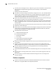
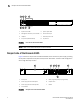
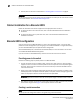
FIGURE 1 Port side of the Brocade 6505
NOTE
The two LEDs on the serial console port are non-functional.
Nonport side of the Brocade 6505
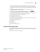
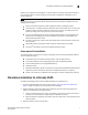
Figure 2 shows the nonport side of the Brocade 6505, which contains the power supply (including
the AC power receptacle and AC power switch) and fan assemblies. The base model configuration
with a single assembly is shown.
FIGURE 2 Nonport side of the Brocade 6505
1 System status LED 5 System power LED
2 Management Ethernet port with LEDs 6 Serial console port
3 USB port 7 Switch ID pull-out tab
4 FC ports 0-3 (all LEDs above) 8 FC ports 4-7
4
2
3
1
6
7
8
5
1 Filler panel 5 Power plug receptacle (with plug retainer)
2 Power supply and fan assembly #1 6 Captive screw
3 Power supply and fan assembly LED 7 Handle
4On/off switch
1 2 3
7
6
4 5