
Reference Guide
44 Fabric OS FCIP Administrator’s Guide
53-1002474-01
Configuration steps
2
Keep-alive timeout option
Consider the following items when configuring the keep-alive timeout option:
• A FICON tunnel requires a keep-alive timeout of less than or equal to 1 second for each FCIP
circuit added to a tunnel.
• If the tunnel is created first with the FICON flag, then the keep-alive timeout for all added
circuits will be 1 second (recommended value for FICON configurations).
• If the tunnel is created with one or more circuits, and then the tunnel is modified to be a FICON
tunnel, then the circuits that were previously created must be modified to have the correct
keep-alive timeout value.
• Set the FCIP circuit keep-alive timeout to the same value on both ends of an FCIP tunnel. If
local and remote circuit configurations do not match, the tunnel will use the lower of the
configured values.
• For normal operations over FCIP tunnels, the keep-alive timeouts for all FCIP circuits in an FCIP
tunnel must be less than the overall I/O timeout for all FC exchanges. If the FC I/O timeout
value is less than the keep-alive timeout value, then I/Os will time out over all available FCIP
circuits without being retried.
The keep-alive value should be based on application requirements. Check with your FC initiator
providers to determine the appropriate keep-alive timeout value for your application. The sum of
keep-alive timeouts for all circuits in a tunnel should be close to the overall FC initiator I/O timeout
value. As an example, a mirroring application has a 6-second I/O timeout. There are three circuits
in the FCIP tunnel. Set the keep-alive timeout to 2 seconds on each FCIP circuit. This will allow for
maximum retries over all available FCIP circuits before an I/O is timed out by the initiator.
Refer to the portcfg fcipcircuit keep-alive timeout option in Table 8 on page 42 for information on
option format and value range.
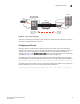
Creating additional FCIP circuits
If the Advanced Extension (FTR_AE) license is enabled, additional FCIP circuits can be created and
added to an FCIP tunnel using the portCfg fcipcircuit create command. The following examples add
a circuit to the tunnel in the basic sample configuration (refer to Figure 12 on page 39).
The following command creates circuit 1 on the FX8-24 end of the tunnel.
switch:admin> portcfg fcipcircuit 8/12 create 1 192.168.11.79 192.168.1.25 -b
15500 -B 62000
The following command creates circuit 1 on the 7800 switch end of the tunnel.
switch:admin> portcfg fcipcircuit 16 create 1 192.168.1.25 192.168.11.79 -b 15500
-B 62000
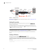
Note the following:
• The VE_Ports used to create the tunnel are the same as specified on the FCIP tunnel in the
basic sample configuration. The VE_Ports uniquely identify the tunnel, and the circuit is
associated with this specific tunnel.
• The unique destination and source IP addresses are mirrored on either end of the tunnel. The
address 192.168.11.79 is the destination address for the FX8-24 blade, and the source
address for the 7800 switch, while the address 192.168.1.25 is the destination address for
the 7800 switch, and the source address for the FX8-24 blade.