53-1001790-01 January 31, 2010 Fan Assembly Replacement Procedure Supporting the PowerConnect B-7500, 7600, and 8000 53-1001790-01 *53-1001790-01*
Notes, Cautions, and Warnings NOTE A NOTE indicates important information that helps you make better use of your computer. CAUTION See the safety and regulatory information that shipped with your system. For additional regulatory information, see the Regulatory Compliance Homepage on www.dell.com at the following location: www.dell.com/regulatory_compliance. CAUTION A CAUTION indicates potential damage to hardware or loss of data if instructions are not followed.
In this guide • Fan assembly replacement . . . . . . . . . . . . . . . . . . . . . . . . . . . . . . . . . . . . . . . • Time required . . . . . . . . . . . . . . . . . . . . . . . . . . . . . . . . . . . . . . . . . . . . . . . . . . • Items required . . . . . . . . . . . . . . . . . . . . . . . . . . . . . . . . . . . . . . . . . . . . . . . . . • Replacing a switch fan assembly . . . . . . . . . . . . . . . . . . . . . . . . . . . . . . . . . .
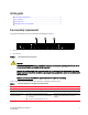
Time required Replacing a fan assembly in the switch should required less than two minutes to complete. Items required The following items are required to replace a fan assembly in the switch: • New single height fan FRU assembly • Phillips-head screwdriver #1. Replacing a switch fan assembly To replace a fan assembly in the switch. 1. With a Phillips-head screwdriver, unscrew the captive screw on the fan assembly. 2. Pull the handle out, away from the chassis. 3.
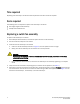
1 2 4 1 Switch 3 Captive Screw 2 Fan Assembly 4 Handle FIGURE 2 3 Inserting the fan assembly in the switch Fan Assembly Replacement Procedure 53-1001790-01 5
Fan Assembly Replacement Procedure 53-1001790-01