Dell PowerConnect W-IAP175 Outdoor Instant Access Point Installation Guide The Dell PowerConnect W-IAP175 is a resilient, environmentally hardened, outdoor rated, dual-radio, dual-band IEEE 802.11 a/b/g/n wireless access point. This outdoor access point is part of Dell’s comprehensive wireless network solution. NOTE: The W-IAP175 requires Instant 3.0 or later. There are three versions of the W-IAP175, which mainly differ in the way they receive power. W-IAP175P: PoE+ powered (802.
Package Contents W-IAP175 Access Point W-IAP175 Mounting Bracket Solar Shield Pole Anchors x 2 M4 x 16 bolts, flat washers, and spring washers x4 (These bolts are attached to the solar shield) M6 x 30 bolts, flat washers, and spring washers x2 M4 x 12 bolt, external-tooth washer, and OT copper lug x1 M8 x 110 bolt, flat washers, spring washers, and nuts x4 Metal Weatherproof Caps x2 for use on unused antenna interfaces RJ-45 Connector Kit with plastic RJ-45 connector (
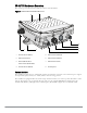
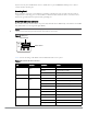
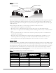
W-IAP175 Hardware Overview The following section describes the hardware features of the W-IAP175. Figure 1 W-IAP175 Overview (W-IAP175P shown) 5 6 4 3 7 2 8 1 1 Antenna Interface (Radio 1) 5 Antenna Interface (Radio 0) 2 USB Console Interface 6 Antenna Interface (Radio 1) 3 Reserved (W-IAP175P) or Power Interface (W-IAP175AC) 7 Ethernet Interface (PoE) 4 Antenna Interface (Radio 0) 8 Grounding Point Antenna Interface The W-IAP175 requires the use of detachable outdoor-rated antennas.
USB Console Interface A USB serial console port is provided for connection to a terminal, allowing direct local management. Use the included USB console cable to connect to the AP. You can download the necessary driver for USB-UART adapter from download.dell-pcw.com under Tools & Resources.
injector. Inversely, the W-IAP175AC can act as a PSE device to provide IEEE802.3af PoE power to devices connected to the ethernet port. Grounding Point Always remember to protect your W-IAP175 by installing grounding lines. The ground connection must be complete before connecting power to the W-IAP175 enclosure. Ensure that the resistance is less than 5 ohm between the ground termination point and the grounding tier.
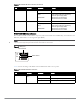
Table 3 W-IAP175P LED Status Indicators (Continued) LED Function Indicator Status RSSI (Radio 0) RSSI Level for Radio 0 Off RSSI disabled/no signal 4 Step Progressive Bars (Red) Each bar represents a progressive increase in signal strength, with 4 bars representing maximum signal strength (100%).
Table 4 W-IAP175AC LED Status Indicators (Continued) LED Function Indicator Status POE Displays PSE power output status Off Non-powered device (0Ω1MΩ) Green Port on (25kΩ) 1 Flash: Low signature resistance (300Ω
Scale Requirements The potentially immense scale of outdoor deployments requires consideration of factors that may not be as important in a typical indoor deployment: Range (distance): Range or distance between APs must be taken into account during the planning phase. Available AP mounting locations are often far less flexible in an outdoor environment.
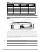
Figure 4 Line of Sight Radio Line of Sight Visual Line of Sight If there are obstacles in the radio path, there may still be a radio link but the quality and strength of the signal will be affected. Calculating the maximum clearance from objects on a path is important as it directly affects the decision on antenna placement and height. It is especially critical for long-distance links, where the radio signal could easily be lost.
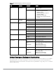
Table 5 Antenna Minimum Height and Clearance Requirements Total Link Distance Max Clearance for 60% of First Fresnel Zone at 5.8 GHz Approximate Clearance for Earth Curvature Total Clearance Required at Mid-point of Link 4 miles (6.4 km) 17.7 ft (5.4 m) 2.0 ft (0.6 m) 19.7 ft (6.0 m) 5 miles (8 km) 20 ft (6.1 m) 3.0 ft (0.9 m) 23 ft (7.0 m) 7 miles (11.3 km) 23.6 ft (7.2 m) 6.2 ft (1.9 m) 30 ft (9.1 m) 9 miles (14.5 km) 27 ft (8.2 m) 10.2 ft (3.1 m) 37 ft (11.3 m) 12 miles (19.3 km) 30.
Antenna Position and Orientation Once the required antenna height has been determined, other factors affecting the precise position of the wireless bridge or mesh link must be considered: Be sure there are no other radio antennas within 2 m (6 ft) of the wireless bridge or mesh link. These include other WiFi radio antennas. Place the wireless bridge or mesh link away from power and telephone lines.
Determine if conduits, bracing, or other structures are required for safety or protection of the cable. For lightning protection at the power injector end of the cable, consider using a lightning arrestor immediately before the cable enters the building Grounding It is important that the wireless bridge or mesh link, cables, and any supporting structures are properly grounded. Each W-IAP175 access point includes a grounding screw for attaching a ground wire.
Connected Antennas” on page 15. For weatherproofing cable connections, see “Weatherproofing Cable Connections” on page 18. NOTE: The following instructions assume that you have installed a lightning arrestor on your W-IAP175.
Figure 7 Cable Connections Connectors on bottom of antenna N-type connector on an RF cable AP175_16 N-type connector on a pigtail Important Points to Remember 14 Do not cover the weep holes on the antennas. Doing so can restrict the release of condensation from the antennas. Proper weatherproofing is not a fast process. Set aside ample time to complete the steps outlined below. When wrapping, make the each layer of tape as flat as possible.
Weatherproofing Directly Connected Antennas NOTE: The following instructions assume that you have installed a lightning arrestor between your W-IAP175. First Wrapping of Tape 1. Before wrapping the antennas, locate the weep holes (Figure 6). Weep holes allow condensation that has built up inside the antenna to escape. 2. Prepare the antenna connector and lightning arrestor by cleaning and drying it. 3. Cut a 4” (100 mm) strip of electrical tape from the roll.
Wrapping of Butyl Rubber 1. Cut a 3/4” (19 mm) strip of butyl rubber. 2. Wrap the strip of rubber around the taped connector (Figure 9) 3. Join the two ends by pushing them together until there is no longer a seam (Figure 10).
Second Wrapping of Tape 1. Cut a 4” (100 mm) strip of electrical tape from the roll. 2. Where you begin wrapping depends on the orientation of the antenna. Water should flow in the opposite direction of the wrapping to prevent water from entering the connector between the layers of tape. Therefore, if the antenna is facing up, you should begin wrapping at the AP end of the connector. This will ensure that your fourth and final layer will be layered correctly.
Weatherproofing Cable Connections First Wrapping of Tape 1. Prepare the antenna connector by cleaning and drying it. 2. Cut a 4” (100 mm) strip of electrical tape from the roll. Pre-cutting the tape into strips makes in easier to maneuver the tape around the connectors and other components but is not required. 3. Beginning at the top of the connector, tightly wrap the connection with a layer of the 3/4” (19mm) electrical tape. Overlap the tape to a half-width. 4.
Wrapping of Butyl Rubber 1. Cut a piece of butyl rubber large enough to wrap around the connector and extended past the first layer of tape. 2. Wrap the strip of rubber around the taped connector (Figure 13) 3. Join the two ends by pushing them together until there is no longer a seam (Figure 14).
Second Wrapping of Tape 1. Cut a 4” (100 mm) strip of electrical tape from the roll. 2. Using 3/4” (19mm) electrical tape, begin wrapping at the connector and create four layers. 3. After completing the fourth layer of tape, check your work to ensure there are no places where water can collect. If there are, you must smooth out those areas with additional layers of tape or remove the weatherproofing and begin again.
Installing the W-IAP175 on a Pole 1. Attach the W-IAP175 on the mounting bracket using the two M6 x30 bolts (with flat and spring washers) on each side of the mounting bracket. AP175_03 Figure 16 Attaching the mounting bracket to the AP 2. Attach the mounting bracket (with W-IAP175) on the pole using four M8 x110 bolts (with flat washers, spring washers and nuts) and the pair of pole anchors.
Installing the W-IAP175 on a Wall 1. Begin by marking the screw points on the wall in the location you have selected. a. Put the mounting bracket on the installation position against the wall. b. Mark four expansion screw holes on the wall. Figure 18 Position of the screw holes 2. Use a drill to create four holes on the four markings you created in the previous step. 3. Install wall (masonry) anchors. a. Insert a masonry anchor into each drilled hole. b.
Figure 19 Attaching the AP to the Mounting Bracket Front Front Grounding the W-IAP175 The grounding must be completed before powering up the W-IAP175. The resistance of grounding wire should be less than 5 ohm and the grounding cable’s cross-section area should be no less than 6 mm.The grounding hole is at the right side of the W-IAP175. Figure 20 Grounding the W-IAP175 AP175_04 1.
Connecting the Ethernet Cable (W-IAP175P) To ensure that your outdoor access point (AP) maintains ethernet connectivity and Power over Ethernet (PoE), you must use the included weatherproof connector kit and install it using the steps below. WARNING: Failure to use the included weatherproof connector kit can lead to connectivity and PoE issues.
Connecting the Ethernet Cable (W-IAP175AC) To ensure that your outdoor access point (AP) maintains ethernet connectivity and Power over Ethernet (PoE), you must use the included weatherproof connector kit and install it using the steps below. WARNING: Failure to use the included weatherproof connector kit can lead to connectivity and PoE issues.
Figure 23 Connecting the Ethernet cable Connecting the Power Cable (W-IAP175 AC) CAUTION: Installation and service of Dell products should be performed by Professional Installers in a manner that is consistent with the electrical code in force in the jurisdiction of deployment. In many countries this will require a licensed electrician to perform this operation. The best practice is to connect to AC mains in an order grade weather protected junction box.
Connecting a Power Cable to the W-IAP175AC 1. Remove the protective cap on the power interface. 2. Insert the power cable connector into the power interface and hand-fasten the waterproof cover. 3. Water-proof the power cable connection with PVC insulation tape, adhesive insulation tape and strap.
Product Specifications Mechanical Dimensions (H x W x D) 10.2 inches x 9.4 inches x 4.1 inches 26 cm x 24 cm x 10.5 cm Weight: 7 lbs/3.25 kg Shipping Dimensions (H x W x D) 12.9 inches x 12.6 inches x 11.8 inches 33 cm x 32 cm x 30 cm Shipping Weight: 16.6 lbs/7.
Wireless LAN AP type: Dual-radio, dual-band 802.11n outdoor Supported frequency bands (country-specific restrictions apply): 2.400 to 2.4835 GHz 5.150 to 5.250 GHz 5.250 to 5.350 GHz 5.470 to 5.725 GHz 5.725 to 5.850 GHz Available channels: virtual controller-managed, dependent upon configured regulatory domain Supported radio technologies: 802.11b: Direct-sequence spread-spectrum (DSSS) 802.11a/g/n: Orthogonal frequency division multiplexing (OFDM) 802.
Safety and Regulatory Compliance Dell provides a multi-language document containing country specific restrictions and additional safety and regulatory information for all Dell hardware products. The Dell PowerConnect W-Series Safety, Environmental, and Regulatory Information document is included with this product. CAUTION: RF Radiation Exposure Statement: This equipment complies with FCC RF radiation exposure limits. This equipment should be installed and operated with a minimum distance of 13.
Proper Disposal of Dell Equipment For the most current information about Global Environmental Compliance and Dell products, see dell.com. Waste of Electrical and Electronic Equipment Dell products at end of life are subject to separate collection and treatment in the EU Member States, Norway, and Switzerland and therefore are marked with the symbol shown at the left (crossed-out wheelie bin).
Philippines Type-Approval No. ESD-CPE-1004995C UAE (W-IAP175P) TRA REGISTERED No: ER0055290/11 DEALER No: DA0039425/10 UAE (W-IAP175AC) TRA REGISTERED No: ER0082364/12 DEALER No: DA0039425/10 Contacting Support Website Support Main Website dell.com Support Website support.dell.com Dell Documentation support.dell.com/manuals Copyright © 2012 Aruba Networks, Inc.