
User guide


B-8 User’s Guide
The system uses a 15-pin high-density D-subminiature connector on the back panel
for attaching a video graphics array (VGA)-compatible monitor to your system. The
video circuitry on the system board synchronizes the signals that drive the red, green,
and blue electron guns in the monitor.
NOTE: Installing a video card automatically disables the system's built-in video
subsystem.
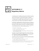
If you reconfigure your hardware, you may need pin number and signal information for
the video connector. Figure B-6 illustrates the pin numbers for the video connector,
and Table B-5 lists and defines the pin assignments and interface signals for the video
connector.
()
&!)
1 RED O Red video
2 GREEN O Green video
3 BLUE O Blue video
4NC — No connection
5-8, 10 GND — Signal ground
9VCC — Vcc
11 NC — No connection
12 DDC data out O Monitor detect data
13 HSYNC O Horizontal synchronization
14 VSYNC O Vertical synchronization
15 DDC clock out O Monitor detect clock
Shell ——Chassis ground
15 11
51
10 6