Dell™ PowerEdge™ 1750 Systems User's Guide System Overview Using the Dell OpenManage Server Assistant CD Using the System Setup Program Technical Specifications Using Console Redirection Glossary NOTE: A NOTE indicates important information that helps you make better use of your computer. NOTICE: A NOTICE indicates either potential damage to hardware or loss of data and tells you how to avoid the problem. CAUTION: A CAUTION indicates a potential for property damage, personal injury, or death.
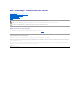
Back to Contents Page Technical Specifications Dell™ PowerEdge™ 1750 Systems User's Guide Technical Specifications Technical Specifications Microprocessor Microprocessor type up to two Intel® Xeon™ microprocessors with a minimum internal operating frequency of at least 2.
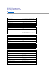
Video Video type ATI Rage XL PCI video controller; VGA connector Video memory 8 MB Power Power supply: Wattage 320 W (AC) Voltage 100–240 VAC, 50/60 Hz, 3.9–2.0 A Heat dissipation 1026 BTU/hr maximum per power supply Maximum inrush current Under typical line conditions and over the entire system ambient operating range, the inrush current may reach 25 A per power supply for 10 ms or less. System battery 3.0-V lithium ion coin cell Physical Height 4.2 cm (1.67 inches) Width 44.7 cm (17.
Back to Contents Page Using Console Redirection Dell™ PowerEdge™ 1750 Systems User's Guide Hardware Requirements Software Requirements Configuring the Host System Configuring the Client System Managing the Host System Remotely Configuring Special Key Functions Console redirection allows you to manage a host (local) system from a client (remote) system by redirecting keyboard input and text output through a serial port. You cannot redirect graphic output.
Console redirection supports only 9600, 19.2 K, 57.6 K, or 115.2 K bps. 5. l Set Data bits to 8. l Set Parity to None. l Set Stop bits to 1. l Set Flow control to Hardware. Click OK. Configuring the Terminal Settings 1. In HyperTerminal, click File, click Properties, and then click the Settings tab. 2. Ensure that the Function, arrow, and Ctrl keys act as field is set to Terminal Keys. 3. Ensure that the Backspace key sends field is set to Ctrl+H. 4.
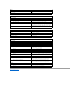
<[> VT 100/220, ANSI <[> VT 100/220, ANSI <[> VT 100/220, ANSI VT 100/220, ANSI VT 100/220, ANSI VT 100/220, ANSI VT 100/220, ANSI VT 100, ANSI VT 100, ANSI <[><1><7><~> VT 100/220 VT 100, ANSI <[><1><8><~> VT 100/220 VT 100, ANSI <[><1><9><~> VT 100/220
Back to Contents Page System Overview Dell™ PowerEdge™ 1750 Systems User's Guide Indicators on the Optional Bezel Front-Panel Features and Indicators Back-Panel Features and Indicators System Features Supported Operating Systems Power Protection Devices Other Documents You May Need Obtaining Technical Assistance Your system is a rack-dense, full-featured, highly available, rack-mount system equipped with one or two Intel® Xeon™ microprocessors.
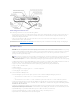
Table 1-2. Front-Panel LED Indicators, Buttons, and Connectors Indicator, Button, or Connector Icon Description blue system status indicator The blue system status indicator lights up during normal system operation. Both the systems management software and the identification buttons located on the front and back of the system can cause the blue system status indicator to flash to identify a particular system.
If the optional RAID on motherboard (ROMB) card is activated, two indicators on each of the hard-drive carriers provide information on the status of the SCSI hard drives. See Figure 1-3 and Table 1-3. The SCSI backplane firmware controls the drive power-on/fault indicator. Figure 1-3. SCSI Hard-Drive Indicators Table 1-3 lists the drive indicator patterns. Different patterns are displayed as drive events occur in the system. For example, if a hard-drive fails, the "drive failed" pattern appears.
Connecting External Devices When connecting external devices to your system, follow these guidelines: l Most devices must be connected to a specific connector and device drivers must be installed before the device operates properly. (Device drivers are normally included with your operating system software or with the device itself.) See the documentation that accompanied the device for specific installation and configuration instructions. l Always attach external devices while your system is turned off.
l Systems management circuitry that monitors operation of the system fans as well as critical system voltages and temperatures. The systems management circuitry works in conjunction with the systems management software. l Back-panel connectors include mouse, keyboard, serial, video, USB, external SCSI, RAC Ethernet, and two NIC connectors. l Front-panel connectors include a video and a USB connector. For more information about specific features, see "Technical Specifications.
Obtaining Technical Assistance If you do not understand a procedure in this guide or if the system does not perform as expected, see your Installation and Troubleshooting Guide. Dell Enterprise Training and Certification is available; see www.dell.com/training for more information. This service may not be offered in all locations.
Back to Contents Page Using the Dell OpenManage Server Assistant CD Dell™ PowerEdge™ 1750 Systems User's Guide Starting the Server Assistant CD Using the Server Setup Program Updating Drivers and Utilities Using the Utility Partition The Dell OpenManage Server Assistant CD contains utilities, diagnostics, and drivers to help you configure your system. You begin the operating system installation with this CD if your operating system was not preinstalled on your system.
Using the Utility Partition The utility partition is a bootable partition on the hard drive that contains system configuration and diagnostic utilities. When you start the utility partition, it boots and provides an executable environment for the partition's utilities. To start the utility partition, turn on or reboot the system.
Back to Contents Page Using the System Setup Program Dell™ PowerEdge™ 1750 Systems User's Guide Entering the System Setup Program System Setup Options System and Setup Password Features Disabling a Forgotten Password Asset Tag Utility After you set up your system, run the System Setup program to familiarize yourself with your system configuration and optional settings. Print the System Setup screens by pressing or record the information for future reference.
Figure 3-1. Main System Setup Program Screen Table 3-2 lists the options and descriptions for the information fields that appear on the main System Setup program screen. NOTE: The System Setup program defaults are listed under their respective options, where applicable. Table 3-2. System Setup Program Options Option Description System Time Resets the time on the system's internal clock. System Date Resets the date on the system's internal calendar.
affect the operation of the keyboard itself if a keyboard is attached to the system. Asset Tag Displays the customer-programmable asset tag number for the system if an asset tag number has been assigned. To enter an asset tag number of up to 10 characters into NVRAM, see "Asset Tag Utility." Integrated Devices Screen Table 3-3 lists the options and descriptions for the information fields that appear on the Integrated Devices screen. Table 3-3.
NOTE: See "Using the Setup Password" for instructions on assigning a setup password and using or changing an existing setup password. Password Status Setting the Setup Password option to Enabled prevents the system password from being changed or disabled at system start-up. To lock the system password, assign a setup password in the Setup Password option and then change the Password Status option to Locked.
NOTE: To escape from the field without assigning a system password, press to move to another field, or press at any time prior to completing step 5. 4. Press . 5. To confirm your password, type it a second time and press . The setting shown for the System Password changes to Enabled. Exit the System Setup program and begin using your system. 6. Either reboot your system now for your password protection to take effect or continue working.
To erase a character when entering your password, press or the left-arrow key. After you verify the password, the Setup Password setting changes to Enabled. The next time you enter the System Setup program, the system prompts you for the setup password. A change to the Setup Password option becomes effective immediately (restarting the system is not required).
Back to Contents Page Glossary Dell™ PowerEdge™ 1750 Systems User's Guide The following list defines or identifies technical terms, abbreviations, and acronyms used in your system documents. A Abbreviation for ampere(s). AC Abbreviation for alternating current. ACPI Abbreviation for Advanced Configuration and Power Interface. adapter card An expansion card that plugs into an expansion-card connector on the computer's system board.
Abbreviation for bits per second. BTU Abbreviation for British thermal unit. bus An information pathway between the components of a system. Your system contains an expansion bus that allows the microprocessor to communicate with controllers for all the various peripheral devices connected to the system. Your system also contains an address bus and a data bus for communications between the microprocessor and RAM. byte Eight contiguous bits of information, the basic data unit used by your system.
Directories help keep related files organized on a disk in a hierarchical, "inverted tree" structure. Each disk has a "root" directory; for example, a c:\> prompt normally indicates that you are at the root directory of hard drive C. Additional directories that branch off the root directory are called subdirectories. Subdirectories may contain additional directories branching off them. DMA Abbreviation for direct memory access.
Abbreviation for feet. FTP Abbreviation for file transfer protocol. g Abbreviation for gram(s). G Abbreviation for gravities. guarding A type of data redundancy that uses a set of physical drives to store data and a single, additional drive to store parity data. Data is protected from the loss of a single drive. Guarding is sometimes preferred over mirroring because it is more cost-effective in systems with a very high storage capacity.
Abbreviation for Internetwork Packet EXchange. IRQ Abbreviation for interrupt request. A signal that data is about to be sent to or received by a peripheral device travels by an IRQ line to the microprocessor. Each peripheral connection must be assigned an IRQ number. For example, the first serial port in your system (COM1) is assigned to IRQ4 by default. Two devices can share the same IRQ assignment, but you cannot operate both devices simultaneously.
MAC Abbreviation for Media Access Control. mAh Abbreviation for milliampere-hour(s). math coprocessor See coprocessor. Mb Abbreviation for megabit. MB Abbreviation for megabyte(s). The term megabyte means 1,048,576 bytes; however, when referring to hard drive storage, the term is often rounded to mean 1,000,000 bytes. MB/sec Abbreviation for megabytes per second. Mbps Abbreviation for megabits per second. MBR Abbreviation for master boot record.
NIC Acronym for network interface controller. NMI Abbreviation for nonmaskable interrupt. A device sends an NMI to signal the microprocessor about hardware errors, such as a parity error. noninterlaced A technique for decreasing screen flicker by sequentially refreshing each horizontal line on the screen. ns Abbreviation for nanosecond(s), one billionth of a second. NTFS Abbreviation for the NT File System option in the Windows NT operating system.
PS/2 Abbreviation for Personal System/2. PXE Acronym for Preboot Execution Environment. RAC Acronym for remote access controller. RAID Acronym for redundant array of independent disks. An array of multiple independent hard drives that, in varying levels, provide high performance and fault tolerance.
hardware. Typically, readme files provide installation information, describe new product enhancements or corrections that have not yet been documented, and list known problems or other things you need to be aware of as you use the software or hardware. ROM Acronym for read-only memory. Your system contains some programs essential to its operation in ROM code. Unlike RAM, a ROM chip retains its contents even after you turn off your system.
l RAM l Controllers for standard peripheral devices, such as the keyboard l Various ROM chips Frequently used synonyms for system board are motherboard and logic board. system configuration information Data stored in memory that tells a system what hardware is installed and how the system should be configured for operation. system diskette System diskette is a synonym for bootable diskette. system memory System memory is a synonym for RAM.
VCCI Abbreviation for Voluntary Control Council for Interference. VDC Abbreviation for volt(s) direct current. VGA Abbreviation for video graphics array. VGA and SVGA are video standards for video adapters with greater resolution and color display capabilities than previous standards. To display a program at a specific resolution, you must install the appropriate video drivers and your monitor must support the resolution.
Back to Contents Page
Back to Contents Page Dell™ PowerEdge™ 1750 Systems User's Guide Notes, Notices, and Cautions Abbreviations and Acronyms Notes, Notices, and Cautions NOTE: A NOTE indicates important information that helps you make better use of your computer. NOTICE: A NOTICE indicates either potential damage to hardware or loss of data and tells you how to avoid the problem. CAUTION: A CAUTION indicates a potential for property damage, personal injury, or death.