
Users Guide

support.dell.com I/O Ports and Connectors B-5
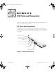
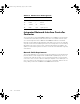
USB Connectors
Your system contains two Universal Serial Bus (USB) connectors for attaching USB-
compliant devices. USB devices are typically peripherals such as mice, printers,
keyboards, and system speakers.
NOTICE: Do not attach a USB device or a combination of USB devices that
draw a maximum current over 500 milliamperes (mA) per channel or +5
volts (V). Attaching devices that exceed this threshold may cause the USB
ports to shut down. See the documentation that accompanied the USB
devices for their maximum current ratings.
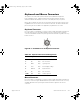
If you reconfigure your hardware, you may need pin number and signal information for
the USB connectors.
Figure B-6 illustrates the USB connector and Tabl e B-5 defines
the pin assignments and interface signals for the USB connector.
Figure B-6. Pin Numbers for the USB Connector
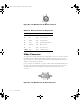
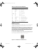
Table B-4. Video Connector Pin Assignments
Pin Signal I/O Definition
1 RED O Red video
2 GREEN O Green video
3 BLUE O Blue video
4 NC N/A No connection
5–8, 10 GND N/A Signal ground
9 VCC N/A Vcc
11 NC N/A No connection
12 DDC data out O Monitor detect data
13 HSYNC O Horizontal synchronization
14 VSYNC O Vertical synchronization
15 DDC clock out O Monitor detect clock
Shell N/A N/A Chassis ground
1D751bk0.book Page 5 Wednesday, August 12, 2015 2:47 PM