™ 'HOO 3RZHU(GJH 6<67(0 %2$5' 83*5$'( ,167$//$7,21 ZZZ GHOO FRP
1RWHV &DXWLRQV DQG :DUQLQJV Throughout this guide, blocks of text may be accompanied by an icon and printed in bold type or in italic type . These blocks are notes, cautions, and warnings, and they are used as follows : NOTE: A NOTE indicates important information that helps you make better use of your computer system.
'HOO 3RZHU(GJH 6\VWHP %RDUG 8SJUDGH ,QVWDOODWLRQ :$51,1* 7KH SRZHU VXSSOLHV LQ WKH 3RZHU(GJH FRPSXWHU V\VWHP SURGXFH KLJK YROWDJHV DQG HQHUJ\ KD]DUGV ZKLFK FDQ FDXVH ERGLO\ KDUP 2QO\ WUDLQHG VHUYLFH WHFKQLFLDQV DUH DXWKRUL]HG WR UHPRYH WKH FRPSXWHU FRYHU DQG DFFHVV DQ\ RI WKH FRPSRQHQWV LQVLGH WKH FRPSXWHU This guide provides instructions for removing the system board from your Dell PowerEdge 4300 system and installing the new system board.
1. Turn off your computer and any peripherals. 2. Ground yourself by touching an unpainted metal surface on the chassis, such as the metal around the card-slot openings at the back of the computer, before touching anything inside your computer. While you work, periodically touch an unpainted metal surface on the computer chassis to dissipate any static electricity that might harm internal components. 3. Disconnect your computer and peripherals from their power sources.
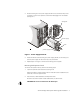
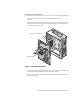
2. Press the locking bar in the power supply handle in and to the left (or lift up if the computer is in rack-mount position) until the latch disengages from the chassis (see Figure 1). locking bar power supply latch power supply handle )LJXUH 3RZHU 6XSSO\ 5HPRYDO 3. Rotate the handle outward (forcing the power supply partially out of its bay), and pull the power supply the rest of the way out by the handle. 4. Repeat steps 1 through 3 to remove the remaining power supplies.
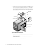
3. For each card you are removing, press in and hold the clip on the back of the computer. At the same time, from inside the computer, press the curved release lever in the middle of the expansion-card latch toward the bottom of the card. After the release lever clicks into the latch cutout, rotate the latch away from the expansion-card bracket. release lever clip latch cutout expansion-card latch expansion card access door door latches (2) )LJXUH ([SDQVLRQ &DUG 5HPRYDO 4.
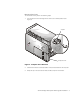
5HPRYLQJ WKH &RYHUV To remove the covers, perform the following steps: 1. Turn the keylock on the back edge of the cover to the unlocked position (see Figure 3). keylock computer cover )LJXUH &RPSXWHU &RYHU 5HPRYDO 2. Slide the cover about a centimeter (half an inch) toward the back of the computer. 3. Grasp the top of the cover at both ends and lift it away from the chassis.
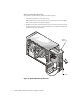
5HPRYLQJ WKH 6\VWHP %RDUG 7UD\ To remove the system board tray, perform the following steps: 1. Disconnect all cables from the system board. When disconnecting the power cables from the system board, press the plastic latch on one side of the connector to release it. 2. Release the tray latch at the lower-back corner of the system board tray (see Figure 4) and pull the tray open to the service position. Then depress the latch again and pull the tray out of the chassis.
5HPRYLQJ WKH 6\VWHP %RDUG To remove the system board from the system board tray, perform the following steps: 1. Loosen the thumbscrew securing the system board to the tray (see Figure 5). 2. Slide the system board to the left as shown in Figure 5 (toward the inner expansion-card guide brackets) about a centimeter (half an inch) to clear the chassis hooks, and remove the board. inner card-guide brackets thumbscrew )LJXUH 6\VWHP %RDUG 5HPRYDO 3.
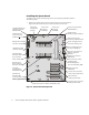
,QVWDOOLQJ WKH 6\VWHP %RDUG To install the new system board (see Figure 6) on the supporting subchassis, perform the following steps: 1. SCSI backplane board interface connector (BACKPLANE) Position the system board over the system board tray so that the slots are aligned with the chassis hooks; then lower the board onto the tray.
2. Slide the system board to the right about a centimeter (half an inch) to lock the board in place (see Figure 7). 3. Secure the system board with the thumbscrew (see Figure 7). thumbscrew )LJXUH 6\VWHP %RDUG ,QVWDOODWLRQ ,QVWDOOLQJ 6\VWHP %RDUG &RPSRQHQWV To install all the components you removed from the original system board on to the new system board, perform the following steps.
3. Install all expansion cards in the same slots on the new system board (use the notes you made when you removed the cards from the original system board). 4. Install any internal panels, shrouds, or brackets. 5. Install the computer cover. 6. Install the power supplies : a. Slide the power supply almost all the way into its bay, allowing it to extend out about a half centimeter (a quarter of an inch). b.
3ULQWHG LQ WKH 8 6 $ ™ & ZZZ GHOO FRP 3 1 3