Dell™ PowerEdge™ 7150 Systems User's Guide System Overview Computer Orientation Removing and Replacing the Bezel Front-Panel Features Bezel and Control Panel Indicators Back-Panel Features System Features Power Protection Devices Other Documents You May Need Safety, Regulatory, and Warranty Information Getting Help Using the EFI Boot Manager and Dell Utilities EFI Boot Manager Dell Utilities PowerEdge 7150 System Support CD Updating or Restoring the System BIOS Using the System Setup Program Entering the Sy
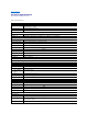
Back to Contents Page Technical Specifications Dell™ PowerEdge™ 7150 Systems User's Guide Table A-1.
Physical Height 31.12 cm (12.25 inches [7 U]) Width 44.45 cm (17.5 inches) Depth 71.12 cm (28.0 inches) Weight 72.5 kg (160 lb), maximum configuration Environmental Temperature: Operating 10° to 35° C (50° to 95° F) Storage -40° to 65° C2 (-40° to 149° F) Relative humidity: Operating 85% (noncondensing at 40° C [104° F]) Storage 95% (noncondensing at 55° C [131° F]) 1 NOTE: Under typical line conditions and over the entire system ambient operating range, the inrush current may reach 140A.
Back to Contents Page I/O Ports and Connectors Dell™ PowerEdge™ 7150 Systems User's Guide Serial and Parallel Ports Keyboard and Mouse Connectors Video Connector USB Connectors Integrated Network Interface Controller Connector This section provides specific information about the computer's I/O ports. The I/O ports and connectors on the back panel of the computer are the gateways through which the computer system communicates with external devices, such as a keyboard, mouse, printer, and monitor.
Table B-1. Pin Numbers for the Serial Port Connectors Pin Signal I/O Definition 1 DCD I Data carrier detect 2 SIN I Serial input 3 SOUT O Serial output 4 DTR O Data terminal ready 5 GND N/A Signal ground 6 DSR I Data set ready 7 RTS O Request to send 8 CTS I Clear to send 9 RI I Ring indicator Shell N/A N/A Chassis ground Parallel Port Connector If you reconfigure your hardware, you may need pin number and signal information for the parallel port connector.
8 PD6 I/O Printer data bit 6 9 PD7 I/O Printer data bit 7 10 ACK# I Acknowledge 11 BUSY I Busy 12 PE Paper end 13 SLCT I Select 14 AFD# O Automatic feed 15 ERR# I Error 16 INIT# O Initialize printer 17 SLIN# O Select in 18–25 GND I N/A Signal ground Keyboard and Mouse Connectors The system uses a Personal System/2 (PS/2)-style keyboard and supports a PS/2-compatible mouse.
Table B-4. Mouse Connector Pin Assignments Pin Signal 1 MCDATA I/O I/O Definition 2 NC N/A No connection 3 GND N/A Signal ground 4 FVcc N/A Fused supply voltage 5 MCCLK I/O 6 NC N/A No connection Shell N/A N/A Chassis ground Mouse data Mouse clock Video Connector The system uses a 15-pin high-density D-subminiature connector on the back panel for attaching a video graphics array (VGA)-compatible monitor to your computer.
NOTICE: Do not attach a USB device or a combination of USB devices that draw a maximum current over 500 mA per channel or +5 V. Attaching devices that exceed this threshold might cause the USB ports to shut down. See the documentation that accompanied the USB devices for their maximum current ratings. If you reconfigure your hardware, you may need pin number and signal information for the USB connectors.
Back to Contents Page
Back to Contents Page System Overview Dell™ PowerEdge™ 7150 Systems User's Guide Computer Orientation System Features Removing and Replacing the Bezel Power Protection Devices Front-Panel Features Other Documents You May Need Bezel and Control Panel Indicators Safety, Regulatory, and Warranty Information Back-Panel Features Getting Help The Dell™ PowerEdge™ 7150 system is a feature-rich, enterprise-class server that offers the highest performance, availability, scalability, manageability, and in
Replacing the Bezel CAUTION: When reinstalling the front bezel, carefully align the bezel to avoid damaging the connector on the back which operates the indicator lights on the front of the bezel. 1. Align the four notches and the connector on the back of the bezel with the four posts and connector on the front of the system. 2. Gently press the bezel onto the front of the computer until it snaps into place. Front-Panel Features Figure 1-3 shows the major features at the front of the computer.
Figure 1-4. Bezel Indicators Control-Panel Indicators The indicators on the computer's control panel described in Table 1-1 are shown in Figure 1-5: Table 1-1.
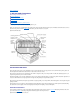
Back-Panel Features Figure 1-6 shows the back-panel features on the computer. Figure 1-6. Back-Panel Features When connecting external devices to your system, follow these guidelines: l Always attach external devices while your system is turned off and the AC power cords are unplugged.
system unless the documentation for the device specifies otherwise. (If the system does not seem to recognize the device, try turning on the system before turning on the device.) l Check the documentation that accompanied the device for specific installation and configuration instructions. For example, most devices must be connected to a particular connector to operate properly. Also, external devices usually require you to install device drivers before they will work.
Power Protection Devices A number of devices are available that protect against potential power problems such as power surges, transients, and power failures. The following subsections describe some of these devices. Surge Protectors Surge protectors are available in a variety of types and usually provide a level of protection commensurate with the cost of the device.
Back to Contents Page Using the EFI Boot Manager and Dell Utilities Dell™ PowerEdge™ 7150 Systems User's Guide EFI Boot Manager Dell Utilities PowerEdge 7150 System Support CD Updating or Restoring the System BIOS This section describes your system's Extensible Firmware Interface (EFI) Boot Manager program, the PowerEdge 7150 System Support CD, and the Dell Utilities program. They provide access to various utilities which you may use to configure your system.
If your system is already on, reboot it. 2. Wait until the system tests are completed. The EFI Boot Manager screen appears. 3. From the EFI Boot Manager main menu, select Utilities. 4. From the Utilities Options menu, select Dell Utilities.
Back to Contents Page Using the System Setup Program Dell™ PowerEdge™ 7150 Systems User's Guide Entering the System Setup Program System Setup Screens Using the Password Features Disabling a Forgotten Password You can use the system setup program as follows: l To change the system configuration information after you add, change, or remove hardware in your system l To set or change user-selectable options—for example, the time or date on your system l To configure integrated devices in your system Af
System Setup Screens The system setup screens display the current setup and configuration information for your system. You can select the following five primary screens: l Main — displays the BIOS version, microprocessor type, and default system setup screen language. You can also set the system time and date and processor retest option from this screen.
NOTE: See the section "Using the Password Features" for instructions on assigning a password and using or changing an existing password. See the section, "Disabling a Forgotten Password" for instructions on disabling a forgotten password. The Security Screen also allows you to enable and configure the Secure Mode option. When the system is in Secure Mode, most input and output devices are disabled until you enter the user password.
Using the Supervisor Password Feature When the supervisor password is enabled, the system prompts you for the supervisor password whenever you enter the system setup program. If system configuration security is a concern, you should operate your system with supervisor password protection. Once the supervisor password is assigned, only those who know the password have full use of the system setup program, including the Security screen.
Back to Contents Page Glossary Dell™ PowerEdge™ 7150 Systems User's Guide The following list defines or identifies technical terms, abbreviations, and acronyms used in Dell user documents. A Abbreviation for ampere(s). AC Abbreviation for alternating current. adapter card An expansion card that plugs into an expansion-card connector on the system's system board. An adapter card adds some specialized function to the system by providing an interface between the expansion bus and a peripheral device.
Eight contiguous bits of information; the basic data unit used by your system. C Abbreviation for Celsius. cache To facilitate quicker data retrieval, a storage area for keeping a copy of data or instructions. For example, your system's BIOS may cache ROM code in faster RAM.
DIN Acronym for Deutsche Industrie Norm. display adapter See video adapter. DMA Abbreviation for direct memory access. A DMA channel allows certain types of data transfer between RAM and a device to bypass the microprocessor. DRAC Acronym for Dell OpenManage Remote Assistant Card. DRAM Abbreviation for dynamic random-access memory. A system's RAM is usually made up entirely of DRAM chips.
Abbreviation for gram(s). G Abbreviation for gravities. GB Abbreviation for gigabyte(s). A gigabyte equals 1024 megabytes or 1,073,741,824 bytes. graphics coprocessor See coprocessor. graphics mode See video mode. GUI Acronym for graphical user interface. h Abbreviation for hexadecimal. A base-16 numbering system, often used in programming to identify addresses in the system's RAM and I/O memory addresses for devices.
connection must be assigned an IRQ number. For example, the first serial port in your system (COM1) is assigned to IRQ4 by default. Two devices can share the same IRQ assignment, but you cannot operate both devices simultaneously. K Abbreviation for kilo-, indicating 1000. KB Abbreviation for kilobyte(s), 1024 bytes. KB/sec Abbreviation for kilobyte(s) per second. Kbit(s) Abbreviation for kilobit(s), 1024 bits. Kbps Abbreviation for kilobit(s) per second.
Abbreviation for milliampere-hour(s). math coprocessor See coprocessor. MB Abbreviation for megabyte(s). The term megabyte means 1,048,576 bytes; however, when referring to hard-disk drive storage, the term is often rounded to mean 1,000,000 bytes. memory A system can contain several different forms of memory, such as RAM, ROM, and video memory.
Acronym for nickel cadmium. NiMH Abbreviation for nickel-metal hydride. NMI Abbreviation for nonmaskable interrupt. A device sends an NMI to signal the microprocessor about hardware errors such as parity errors. noninterlaced A technique for decreasing screen flicker by sequentially refreshing each horizontal line on the screen. ns Abbreviation for nanosecond(s), one billionth of a second. NVRAM Abbreviation for nonvolatile random-access memory.
Abbreviation for pin grid array, a type of microprocessor socket that allows you to remove the microprocessor chip. pixel Arranged in rows and columns, a pixel is a single point on a video display. Video resolution—640 x 480, for example—is expressed as the number of pixels across by the number of pixels up and down. POST Acronym for power-on self-test. Before the operating system loads when you turn on your system, the POST tests various system components such as RAM, the disk drives, and the keyboard.
A read-only file is one that you are prohibited from editing or deleting. A file can have read-only status if: Its read-only attribute is enabled. It resides on a physically write-protected diskette. It is located on a network in a directory to which the system administrator has assigned read-only rights to you. refresh rate The frequency, measured in Hz, at which the screen's horizontal lines are recharged. A monitor's refresh rate is also referred to as its vertical frequency.
As the main circuit board, the system board usually contains most of your system's integral components, such as the following: l Microprocessor l RAM l Expansion-card connectors l Controllers for standard peripheral devices such as the keyboard l Various ROM chips Frequently used synonyms for system board are motherboard and logic board. system diskette System diskette is a synonym for bootable diskette. system memory System memory is a synonym for RAM.
colors that a program can display depends on the capabilities of the monitor, the video driver, and the amount of memory installed for the video adapter. VGA feature connector On some systems with an integrated VGA video adapter, a VGA feature connector allows you to add an enhancement adapter, such as a video accelerator, to your system. A VGA feature connector can also be called a VGA pass-through connector.
Back to Contents Page Dell™ PowerEdge™ 7150 Systems User's Guide Notes, Notices, Cautions, and Warnings Notes, Notices, Cautions, and Warnings NOTE: A NOTE indicates important information that helps you make better use of your computer. NOTICE: A NOTICE indicates either potential damage to hardware or loss of data and tells you how to avoid the problem. CAUTION: A CAUTION indicates a potentially hazardous situation which, if not avoided, may result in minor or moderate injury.
Back to Contents Page Figures Dell™ PowerEdge™ 7150 Systems User's Guide Figure 1-1. Computer Orientation (top view) Figure 1-2. Removing the Bezel Figure 1-3. Front-Panel Features Figure 1-4. Bezel Indicators Figure 1-5. Control-Panel Indicators Figure 1-6. Back-Panel Features Figure B-1. Back-Panel Features Figure B-2. Pin Numbers for the Serial Port Connectors Figure B-3. Pin Numbers for the Parallel Port Connector Figure B-4. Pin Numbers for the Keyboard Connector Figure B-5.
Back to Contents Page Tables Dell™ PowerEdge™ 7150 Systems User's Guide Table 1-1. Control-Panel Indicators Table 3-1. System Setup Navigation Keys Table A-1. Technical Specifications Table B-1. Pin Numbers for the Serial Port Connectors Table B-2. Parallel Port Pin Assignments Table B-3. Keyboard Connector Pin Assignments Table B-4. Mouse Connector Pin Assignments Table B-5. Video Connector Pin Assignments Table B-6.