Dell PowerEdge C410x Hardware Owner’s Manual
Notes, Cautions, and Warnings NOTE: A NOTE indicates important information that helps you make better use of your computer. CAUTION: A CAUTION indicates potential damage to hardware or loss of data if instructions are not followed. WARNING: A WARNING indicates a potential for property damage, personal injury, or death. Information in this publication is subject to change without notice. © 2010-2013 Dell Inc. All rights reserved.
Contents NOTES, CAUTIONS, AND WARNINGS .................................................................................................................. 1 CONTENTS ......................................................................................................................................................... 3 1 INTRODUCTION ............................................................................................................................................ 6 POWER SEQUENCE .................
Replacing Power Distribution Board (PDB) .......................................................................................................... 52 Installing the power distribution board ............................................................................................................... 58 IPASS BOARD ............................................................................................................................................................... 59 Replacing iPass Board .........
SAFETY FIRST—FOR YOU AND YOUR SYSTEM ........................................................................................................................... 99 Checking GPU Card ............................................................................................................................................ 100 Checking iPass Cable ..........................................................................................................................................
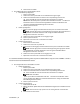
1 Introduction Power Sequence It is recommended that the following power sequence be followed when using the C410x and BMC 1.34 (or newer) with a host server not Intel E5-2600 Series based: 1. 2. For a single host server connected to a C410x: a. Power Up Sequence: i. Power up the C410x. ii. Wait for the Green power LEDs on the individual PCI cages to light. iii. Power up the host server. b. Power Down Sequence: i. Power down the host server. ii. Wait for the host server to power off. iii.
ii. Wait for the Green power LEDs on the individual PCI cages to light. iii. Power up the host server. b. Power Down Sequence: i. Power down the C410x. ii. Wait for the Green power LEDs on the individual PCI cages to turn off and the fans to turn off. NOTE: The host server may report errors of missing devices on the PCIe bus. 2. iii. Power down the host server. iv. Wait for the host server to power off. For multiple host servers connected to a C410x: a. Initial Power Up Sequence: i.
4. iii. Power down the C410x. For multiple host servers connected to a C410x: a. Initial Power Up Sequence: i. Power up the C410x. ii. Wait for the Green power LEDs on the individual PCI cages to light. iii. Wait for the Blue UID LED on the left ear tab to stop blinking and then turn off. When the UID LED turns off the PCIe bus initialization is complete. NOTE: After the C410x power up the PCIe bus initialization will start.
4. iv. Wait for the host server to power off. For multiple host servers connected to a C410x: a. Initial Power Up Sequence: i. Power up the C410x. ii. Wait for the Green power LEDs on the individual PCI cages to light. iii. Wait for the Blue UID LED on the left ear tab to stop blinking and then turn off. When the UID LED turns off the PCIe bus initialization is complete. NOTE: After the C410x power up the PCIe bus initialization will start.
iii. Power up the host server. iv. Repeat for each host server connected to the C410x. b. Power Down Sequence: i. Power down the host server. ii. Wait for the host server to power off. iii. Power down the PCI cage(s) associated with the iPass port connected to the C410x. NOTE: The PCI cage power can be removed by pressing the cage power button or using IPMITool commands identified in the “Using the C410x Base Board Management Controller” document. iv.
2 Product Overview A Tour of the System The following sections describe the external features of the Dell PowerEdge C410X server.
Figure 2 – Back View 1 Power Module 1 11 iPass connector 6 2 Power Module 2 12 iPass connector 7 3 Power Module 3 13 iPass connector 8 4 Power Module 4 14 PCI Cage 11 5 BMC LAN Cable 15 PCI Cage 12 6 iPass connector 1 16 PCI Cage 13 7 iPass connector 2 17 PCI Cage 14 8 iPass connector 3 18 PCI Cage 15 9 iPass connector 4 19 PCI Cage 16 10 iPass connector 5 Product Overview | 12
System LEDs Description Front System LEDs The front system LEDs contain System LED, Power LED and UID LED information. The detailed LEDs information is listed below: Figure 3 – Front System LEDs Table 1-1. Front System LEDs System LED UID LED Displays status/errors and is controlled by BMC. Color Condition Occurrence Amber Blink Fast Power supply fail On FAN fail or sensor error Blink GPU card fail Lights when front or rear ID button is pressed.
Static / Dynamic IP Switch Function Instruction To switch from DHCP to static or vice versa: Hold down the ID button for 5 seconds While pressing the ID button, press and hold the power button for 5 seconds Release the power button, and then the ID button It will take ~30 seconds to change the configuration The ID light will indicate which mode has been selected: - Solid for 5 seconds indicates static IP - Flashing for 5 seconds indicates DHCP If the default IP address is changed, sw
3 Removing and Installing Hardware Safety Measures CAUTION: Many repairs may only be done by a certified service technician. You should only perform troubleshooting and simple repairs as authorized in your product documentation, or as directed by the online or telephone service and support team. Damage due to servicing that is not authorized by Dell is not covered by your warranty. Read and follow the safety instructions that came with the product.
Removing and Installing Hardware | 16
2. Remove the middle top cover from the system. 3. Loosen and remove the screws securing the back cover.
4. Slide the cover horizontally to the back using the traction pad and remove the back cover in the direction of the arrow. NOTE: This system must be operated with the system cover installed to ensure proper cooling. Installing the system cover To install the system cover follow the instructions for removing the system cover in the reverse order.
PCI Cage Removing the PCI Cage NOTE: • Take note of the drive tray orientation before sliding it out. • The tray will not fit back into the bay if inserted incorrectly. 1. Lift the release lever and pull on the cage handle at the same time. 2. Slide the cage assembly out of the system.
Installing the PCI cage To install the PCI cage follow the instructions for removing the PCI cage in the reverse order. PCIe Card Replacing PCIe Card CAUTION: Before you remove or install the PCIe card, press PCI cage power button to turn off the specific single PCI cage power before replacing PCIe card. Follow these instructions to replace a PCIE card: For M1060 Card 1. See to Chapter 4 Cable Routings on page 57 to connect switch button cable and PCI power cable. 2.
3. Secure the card in place with screws and place the PCI side cover as shown in the illustration. 4. Secure the PCI side cover and back cover in place with screws. Installing the M1060 card To install the M1060 card follow the instructions for removing the M1060 card in the reverse order.
For M2050/M2070/M2070Q/M2075/M2090 Cards 1. Connect PCI power cable. 2. Insert the PCIe card by 45 degree and push it into the socket vertically. CAUTION: Care should be taken to prevent damage to components on the back side of the PCIe card. Make sure the card does not drag across the card mounting standoffs of the cage when inserting the card into the socket. 3. Secure the card with screw. 4. Attach the support bracket on the PCIE board and secure it in place with 4 screws.
5. Connect power cable to card as shown. 6. Replace the side cover. 7. Secure the side cover with 4 screws.
8. Secure the PCIE side cover with 3 screws as illustration arrow show.
Installing the Intel 5110P Card Follow the instructions to install the Intel 5110P card. 1. Attach two support brackets with screws to the 5110P card heatsink cover.
2. Connect power cable to card as shown. CAUTION: Make sure the power cable is plugged before inserting the PCIe card into socket. 3. Insert the 5110P card into the socket as shown in the illustration. CAUTION: Care should be taken to prevent damage to components on the back side of the PCIe card. Make sure the card does not drag across the card mounting standoffs of the cage when inserting the card into the socket.
4. Secure the 511P card with 3 screws.
Removing the 5110P card Follow the instructions to remove the Intel 5110P card. 1. Remove the 3 securing screws. 2. Remove the 5110P card from the socket. CAUTION: Care should be taken to prevent damage to components on the back side of the PCIe card. Make sure the card does not drag across the card mounting standoffs of the cage when removing the card from the socket. 3. Unplug power cable as shown. CAUTION: Make sure the card is completely removed from the socket before unplugging the power cable.
4. Remove the securing screws and the support bracket from the 5110P heatsink cover.
Installing the NVIDIA K10/K20 Card Follow the instructions to install the NVIDIA K10/K20 card. 1. Remove the 5 securing screws of K10 heatsink top cover. Remove the 8 securing screws of K20 heatsink top cover. NOTE: Please keep heatsink top cover and securing screws. The heatsink top cover should be attached to replaced card before returning.
2. Attach the support bracket with two screws to the K10/K20 card. Screw 2 3. Insert the K10/K20 card into the socket as shown in the illustration. CAUTION: Care should be taken to prevent damage to components on the back side of the PCIe card. Make sure the card does not drag across the card mounting standoffs of the cage when inserting the card into the socket.
4. Secure the K10/K20 card with 3 screws.
5. Attach K10 support bracket. NOTE: Use the right mounting holes to secure the mounting bracket for the K10 card. Attach the K20 support bracket. NOTE: Use the left mounting holes to secure the mounting bracket for the K20 card. NOTE: Picture is showing a K10 card for a K20 installation.
6. Secure the K10 support bracket with 3 screws. Secure the K20 support bracket with 3 screws. NOTE: Picture is showing a K10 card for a K20 installation.
7. Connect power cable to card.
Removing the NVIDIA K10/K20 Card Follow the instructions to remove the NVIDIA K10/20 card. 1. Unplug power cable as shown. 2. Remove the K10 3 securing screws. Remove the K20 3 securing screws.
3. Remove the K10 support bracket. Remove the K20 support bracket.
4. Remove the 3 securing screws. 5. Remove the card from the socket. CAUTION: Care should be taken to prevent damage to components on the back side of the PCIe card. Make sure the card does not drag across the card mounting standoffs of the cage when removing the card from the socket.
6. Remove the securing screws and the support bracket from K10/K20 card. 7. Attach the heatsink top cover to the K10 card and secure with 5 screws. NOTE: The heatsink top cover must be assembled to the K10 card before it is returned for replacement.
Attach the heatsink top cover to the K20 card and secure with 8 screws. NOTE: The heatsink top cover must be assembled to the K20 card before it is returned for replacement.
Replacing System Fans In case of system fan failure, you can quickly replace the system fan. CAUTION: Before you remove or install the system fans, take the steps: 1) Make sure the system is not turned on or connected to the AC power. 2) Disconnect all necessary cable connections. Failure to observe these warnings could result in personal injury or damage to the equipment. Follow the instruction to remove the system fans: 1. Loosen and remove the screws securing the middle cover.
2. Remove the middle top cover from the system. 3. Lift the system fan ears.
4. Lift the system fan out of the system fan cage. Installing the system fans To install the system fans follow the instructions for removing the system fans in the reverse order.
Fan cage Replacing System Fan Cage CAUTION: Before you remove or install the system fan cage, take the steps: 1) Make sure the system is not turned on or connected to the AC power. 2) Disconnect all necessary cable connections. Failure to observe these warnings could result in personal injury or damage to the equipment. 1. Loosen and remove the screws securing the middle cover.
2. Remove the middle top cover from the system. 3. Loosen and remove the screws securing the fan cage.
4. Lift the fan cage out of the system. NOTE: Watch the fan status LED cables as the fan cage is lifted out of the system. The fan status LED connector should be unplugged before removing the fan cage completely from the system.
5. Remove the fans from the fan cage.
6. Loosen and remove the screws on top of the system fan cage. Installing the system fan cage To install the system fan cage follow the instructions for removing the system fan cage in the reverse order.
Power supply Replacing Power Supplies In case of a power supply failure, you can quickly replace the power supply unit. Follow these instructions to remove the power supply: CAUTION: In order to reduce the risk of injury from electric shock, disconnect AC power from the power supply before removing it from the system. 1. Pull up the power supply handle.
2. Press the retaining clip on the right side of the power supply along the direction of the arrow. 3. At the same time, pull out the power supply by using its handle. NOTE: It takes considerable force to remove the power supply.
Follow these instructions to install the power supply: Insert the replacement power supply firmly into the bay. The retaining clip should snap. Fold the power supply handle down. Connect the AC power cord to the replaced power supply.
Power Distribution Board (PDB) Replacing Power Distribution Board (PDB) Follow these instructions to remove the PDB: CAUTION: Before you remove or install the power distribution board take the steps: 1) Make sure the system is not turned on or connected to the AC power. 2) Disconnect all necessary cable connections. Failure to observe these warnings could result in personal injury or damage to the equipment. 1.
3. Remove the middle top cover from the system. 4. Loosen and remove the screws securing the back cover.
5. Slide the cover horizontally to the back using the traction pad and remove the back cover in the direction of the arrow. 6. Then Remove the BMC LAN cable from the retention clip. Lay the BMC LAN cable across the fans out of the way.
7. Loosen and remove the screws securing the power supply cage. 8. Slide the power cage horizontally to the back.
9. Lift the power cage to remove it in the direction of the arrow. 10. Loosen and remove the screw securing the rail.
11. Remove the rail by lifting the retention clip and at the same time slide the rail in the direction of the arrow. 12. Loosen and remove the screws securing the PDB.
13. Remove the PDB in the direction of the arrow. NOTE: It takes considerable force to remove the PDB. Installing the power distribution board To install the power distribution board follow the instructions for removing the power distribution board in the reverse order. .
iPass Board Replacing iPass Board Follow these instructions to replace the iPass board: CAUTION: Before you remove or install the iPass Board, take the steps: 1) Make sure the system is not turned on or connected to the AC power.2) Disconnect all necessary cable connections. Failure to observe these warnings could result in personal injury or damage to the equipment. 1. Loosen and remove the screws securing the middle cover.
2. Remove the middle top cover from the system. 3. Loosen and remove the screws securing the back cover.
4. Slide the cover horizontally to the back using the traction pad and remove the back cover in the direction of the arrow. 5. Then Remove the BMC LAN cable from the retention clip. Lay the BMC LAN cable across the fans out of the way.
6. Pull up the power supply handle. 7. Remove the power supply in the direction of the arrow.
8. Loosen and remove the screws securing the power supply cage. 9. Slide the power cage horizontally to the back.
10. Lift the power cage to remove it in the direction of the arrow. 11. Loosen and remove the screws securing the top of the iPass connector cage.
12. Slide the iPass connector cage horizontally to the back. 13. Loosen and remove the screws securing the top iPass board.
14. Lift up the iPass board and remove it from the system. 15. Loosen and remove the screws securing the bottom iPass board.
16. Lift up the iPass board and remove it from the system. Installing the iPass board To install the iPass board follow the instructions for removing the iPass board in the reverse order.
Middle Board Replacing Middle Board Follow these instructions to replace the middle board: CAUTION: Before you remove or install the middle board, take the steps: 1) Make sure the system is not turned on or connected to the AC power. 2) Disconnect all necessary cable connections. Failure to observe these warnings could result in personal injury or damage to the equipment. 1. Remove the Fan Cage. See Section- Replacing Fan Cage. 2. Remove the Power Distribution Board.
5. Lift the middle board out of the system in the direction of the arrow, front edge first , to clear the IO ports. Installing the system middle board To install the system middle board follow the instructions for removing the system middle board in the reverse order.
Front I/O Panel Removing Front I/O Panel CAUTION: Before you remove or install the Front I/O Panel, make sure the system is not turned on or connected to the AC power. 1. Remove the screws securing the Front I/O panel cover. 2. Remove the Front I/O panel cover.
3. Remove the screws securing the Front I/O panel. 4. Remove the Front I/O panel and disconnect the cable. Installing the Front IO panel To install the Front IO panel follow the instructions for removing the Front IO panel in the reverse order.
Installing the Rail and the System Follow these instructions to install the rail into a rack: 1. Install the sliding rails into the rack. 2. Align the inner rails with the sliding rails of the rack.
3. Push the system into the sliding rails until the locking latch clicks into place. 4. Connect ipass connectors and power connectors.
NOTE: The 1400W Power Supplies require 220VAC.
4 Cable Routings 1 Fan Power Cable 2 Front I/O Cable 3 BMC LAN Cable 4 Fan LED Cable 5 PCI Power Cable 6 Switch Cable Cable Routings | 75
iPass Port Mapping 2 to 1 mode 4 to 1 mode IPASS Mapping1 1 PCIE VS 5 Mapping2 2 VS 6 Mapping3 3 VS 7 Mapping4 4 8 VS IPASS 1,15 1 2,16 5 3,13 2 4,14 6 5,11 3 6,12 7 7,9 4 8,10 8 NOTE: The default port mapping is 2 to 1 mode.
5 BMC Remote Management Console This chapter provides information on the various functions of the Dell Remote Management Console GUI’s (Graphics User Interface). Initial Configuration using a DHCP Server Before entering the Dell Remote Management Console, you need to connect the DHCP server in the subnet to which it is physically connected. If a DHCP server is found, it may provide a valid IP address, gateway address and net mask.
Static/DHCP IP Controlled by Front Panel Button To switch from DHCP to static or vice versa: Hold down the ID button for 5 seconds While pressing the ID button, press and hold the power button for 5 seconds Release the power button, and then the ID button It will take ~30 seconds to change the configuration The ID light will indicate which mode has been selected: - Solid for 5 seconds indicates static IP - Flashing for 5 seconds indicates DHCP If the default IP address is changed, sw
Remote Management Console Overview 1. 2. 3. Open a web browser and type in your identified IP. The IP address can be found using your DHCP server. A dialog box prompts you to enter Username and Password. Enter the following values: Username: root Password: root NOTE: The default user name and password are in lower-case characters. NOTE: When you log in using the root user name and password, you have full administrative privileges. It is advised that once you log in, you should change the root password.
Enter Dell Remote Management Console After you successfully log in to your Dell Remote Management Console, the Remote Management Console GUI appears. Properties Properties displays the firmware version of current remote client system.
Configuration Network You can view and modify the network settings on this screen. Select whether to obtain an IP address automatically or configure one manually. It is recommended to use DHCP if your environment has a DHCP server. You can set DHCP (obtain the IP address automatically) or STATIC IP (configure the IP address manually). When you finish configuration, click Apply Changes or for re-configuration click Refresh.
Security Security shows the current certificate status. To generate a new certificate, click Generate Certificate. To upload a certificate, click Upload Certificate.
Users To configure a specific user, click the Users ID. To display new user information, click Refresh. Please note that BMC convention for enabling an 'anonymous' login is to configure the entry for User ID 1 with a null username (all zero’s) and a null password (all zero’s). Applications may then present this to the user as an anonymous login.
Services You can configure the web server parameters (such as, HTTP Port Number, HTTPS Port Number, and Timeout) on a remote computer. By default, the timeout is 1800 seconds; 5 for the Max Sessions and 1 for the Active Sessions. When you finish the configuration, click Apply Changes.
IPMI This screen contains two sections: IPMI Serial and IPMI Settings. IPMI Serial There are three serial configuration in IPMI Serial: Connection Mode Settings, Baud Rate, and Channel Privilege Level Limit. The Connection Mode Settings allows user to select the Console redirection type and to manage the system from a remote location. Once the connection mode is set, select the Baud Rate from the drop-down list.
IPMI Settings IPMI Settings provides remote configuration over LAN. To activate IPMI remote configuration by LAN, check Enable IPMI Over LAN option, define the Channel Privilege Level Limit, and enter the Encryption Key. When you finish the configuration, click Apply Changes.
Sessions This screen displays information on Active Sessions. Additionally, the trash can icon provides the delete function for privileged users. Click Refresh to refresh the Sessions status.
Updates The firmware can be updated remotely. To update firmware, follow the instruction below: 1. Select the file on your local system using Browse. 2. Select Update Type. 3. Select Preserve Configuration. 4. Click Update to delete the current version and update to the new version. NOTE: BMC firmware update should not be interrupted, any interruption may result unrecoverable firmware crash? ROM replacement is required to bring C410x back.
Utilities Utilities provides BMC reboot and Factory default restore functions. To reboot system, click Reboot. To restore factory default, click Factory Default.
Server Information Power Control The Power Control allows you to power on/off/cycle the remote host system. Additionally you can see the remote power status. To perform the power control operation, select the operation and click Apply Changes.
Power Consumption This screen displays information on the system power consumption. The information includes Current Power Consumption, Power Consumption Monitoring Start Date, Max/Min Power Consumption, and Average Power Consumption.
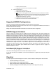
GPU Power Consumption This screen displays the status of GPU power consumption. Each sensor displays different color to indicate the health status of a specified GPU device. The green color indicates the device is healthy and there’s no sensor that has any alert. The yellow color indicates the device has at least one sensor that has warning alert. The red color indicates the device has at least one sensor that has a critical alert.
Thermal This screen displays the Fans and Temperatures sensors of a remote host system. Click Refresh to update current health status for both Fans and Temperatures. The green color indicates the device is healthy and there’s no sensor that has any alert. The yellow color indicates the device has at least one sensor that has a warning alert. The red color indicates the device has at least one sensor that has a critical alert.
System Event Log System Event Log: It records the event when sensor has an abnormal state. When the log matches the pre-defined alert, the system sends out the notification automatically, if it is pre-configured.
Platform Events A platform event filter (PEF) can trigger an action and generate an alert when a critical hardware-related event occurs. For each PEF, you can choose the action to be taken when a platform event occurs. You can also choose to generate and send an alert when a platform event occurs. In the Platform Events screen, you can enable the generation of platform event alerts globally by clicking Global Alerting Enable. When you finish the configuration, click Apply Changes.
Traps Settings In the Trap Settings, user can set the IPv4 and Ipv6 Destination List. IPv6 and IPv4 are two completely separate protocols. IPv6 is not backwards compatible with IPv4, and IPv4 hosts and routers will not be able to deal directly with IPv6 traffic. IPv6 has a significantly larger address space than IPv4. This results from the use of a 128-bit address, whereas IPv4 uses only 32 bits. When you finish the configuration, click Apply Changes.
Email Settings If you want the alert to be sent by email, you can configure to specify the e-mail address, subject and message in the Email Settings. After you finish the configuration, click Apply Change to save the settings.
Port Map User can identify the specified iPASS mapping to PCIE controller in Port Map. Click Apply Change to save the settings.
6 Troubleshooting Your System Safety First—For You and Your System WARNING: Whenever you need to lift the system, get others to assist you. To avoid injury, do not attempt to lift the system by yourself. CAUTION: Before removing the system cover, turn off all power, then unplug the AC power cord, and then disconnect all peripherals, and all LAN lines. CAUTION: Many repairs may only be done by a certified service technician.
Checking GPU Card 1. Power off and remove the middle cover. See section-Removing System Cover to remove the middle cover. 2. Power on the system and PCIe device and check if the GPU card LED lights. 3. If not, see Check iPass cable. Checking iPass Cable 1. Check if iPass cable is properly connected. 2. If the iPass cable is not plugged in correctly, power off the sytem and plug-in the iPass cable again. 3. If not, swap iPass cable.
Checking iPass Connector to Host System 1. Check the Board to Board (BTB) connectors to the iPass Boards. 2. Check System SMBus device routing table. IPASS TOP IPASS Bottom iPass 1: Slot 1/15 iPass 5: Slot 2/16 iPass 2: Slot 3/13 iPass 6: Slot 4/14 iPass 3: Slot 5/11 iPass 7: Slot 6/12 iPass 4: Slot 7/9 iPass 8: Slot 8/10 Check if iPass Board (GS-IPASS2 / GS-IPASS3) is installed properly 1. 2. 3. See Replacing iPass Board on page 40 for instructions to accessing the iPass boards.
7 Jumpers and Connectors Dell PowerEdge C410X Middle Board Connectors and Jumpers Figure 5 identifies critical components on the Dell PowerEdge C410X middle board. Figure 5 – Middle Board Connectors and Jumpers Item Component 1. PCI-E connectors 2. PCI-E connectors 3. Power connectors 4. iPass board connectors 5. Battery 6. Front I/O connector 7. FAN connectors 8. FAN LED connectors 9.
8 Getting Help Contacting Dell For customers in the United States, call 800-WWW-DELL (800-999-3355). NOTE: If you do not have an active Internet connection, you can find contact information on your purchase invoice, packing slip, bill, or Dell product catalog. Dell provides several online and telephone-based support and service options. Availability varies by country and product, and some services may not be available in your area. To contact Dell for sales, technical support, or customer service issues: 1.
9 Index back view, 3 replacing, 44 cable routings, 51 middle board connectors and jumpers, 7 checking GPU card, 77 PCI Cage, 11 checking iPass cable, 78 platform events, 73 checking iPass connector, 79 Port Map, 76 checklist, 1 power consumption, 69 configuring power distribution board IPMI, 61 removing, 27, 44 network, 57 power supplies, 24 security, 58 rail and system services, 60 installing, 48 sessions, 63 user, 59 remote management console overview, 55 email settings, 75 safety