Dell PowerEdge C6320 Owner's Manual Regulatory Model: B08S Regulatory Type: B08S003 July 2020 Rev.
Notes, cautions, and warnings NOTE: A NOTE indicates important information that helps you make better use of your product. CAUTION: A CAUTION indicates either potential damage to hardware or loss of data and tells you how to avoid the problem. WARNING: A WARNING indicates a potential for property damage, personal injury, or death. © 2017 - 2018 Dell Inc. or its subsidiaries. All rights reserved. Dell, EMC, and other trademarks are trademarks of Dell Inc. or its subsidiaries.
Contents Chapter 1: Dell PowerEdge C6320 product overview......................................................................8 Supported configurations for PowerEdge C6320 system.........................................................................................8 Accessing system features during startup.................................................................................................................... 9 Front panel features and indicators...............................................
Boot Manager main menu......................................................................................................................................... 60 PXE boot.............................................................................................................................................................................. 61 Chapter 6: Installing and removing system components.............................................................. 62 Safety instructions..........................
Removing a processor ...............................................................................................................................................95 Installing a processor .................................................................................................................................................96 Expansion card assembly and expansion card ...........................................................................................................
Hard drive backplanes.................................................................................................................................................... 142 Removing the hard drive backplane...................................................................................................................... 144 Installing the hard drive backplane........................................................................................................................ 146 2.
Troubleshooting expansion cards.................................................................................................................................178 Troubleshooting processors.......................................................................................................................................... 179 Chapter 9: Getting help............................................................................................................. 180 Contacting Dell EMC.......................
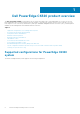
1 Dell PowerEdge C6320 product overview The Dell PowerEdge C6320 is an ultra-dense 2U server that can support up to four independent two-socket (2S) servers. Each independent server features dual Intel Xeon E5-2600v3 or Intel Xeon E5-2600v4 series processors with up to 22 cores, C612 chipset for I/O connectivity, DDR4 memory, dual-port embedded 10 Gigabit Ethernet controllers (SFP+), and integrated iDRAC8 systems management with a dedicated RJ45 connection.
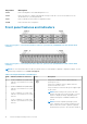
Figure 1. Supported configurations for C6320 Accessing system features during startup The following keystrokes provide access to system features during startup. NOTE: The hot keys of SAS or SATA card or PXE support are available in BIOS boot mode only. There is no hot key to boot in the UEFI mode. Keystroke Description F2 Enters the System Setup program. F11 Enters the BIOS Boot Manager. F12 Starts Preboot eXecution Environment (PXE)/iSCSI boot.
Keystroke Description Ctrl+Y Enters the MegaPCLI SAS RAID Management Tool. Ctrl+S Enters the utility to configure onboard LAN settings for PXE boot. For more information, see the documentation for your integrated LAN. Ctrl+I Enters onboard SATA Controller’s Configuration Utility. Ctrl+D Enters the Intel iSCSI setup menu. Front panel features and indicators Figure 2. Front panel − 3.5-inch x12 hard drives with four system boards (C6320 RAID card and onboard SATA controller) Figure 3.
Table 1. Front panel features and indicators (continued) Item Indicator, button or connector Icon Description NOTE: To force an ungraceful shutdown, press and hold the power button for 5 seconds.
Figure 5. 2.5-inch hard drive indicators 1. hard drive status indicator (green and amber) 2. hard drive activity indicator (green) Table 2.
Back panel features and indicators Figure 6. Back panel with four system boards Table 3. Back panel features and indicators Item Indicator, button, or connector Icon Description 1 PSU 2 Up to 1400 W AC, 1600 W AC, or 1400 HVDC PSUs. 2 PSU 1 Up to 1400 W AC, 1600 W AC, or 1400 HVDC PSUs. 3 USB port Enables you to connect USB devices to the system. The ports are USB 3.0-compliant. 4 Ethernet connector 10G NIC 1 connector. 5 Ethernet connector 10G NIC 2 connector.
Table 3. Back panel features and indicators (continued) Item Indicator, button, or connector Icon Description graceful shutdown before the system is turned off. NOTE: To force an ungraceful shutdown, press and hold the power button for five seconds. 10 System identification indicator The management software of both the systems and the identification buttons on the front can cause the indicator to flash blue to identify a particular system and system board.
Table 4. LAN indicator codes (continued) Component Indicator Condition Activity indicator Blinking green Activity is present: ● Pre OS POST ● OS without driver ● OS with driver Blinking at speed relative to packet density. Off No link/activity present ● D0 (uninitialized) ● D3 (cold) ● S4 (hibernation) Figure 9. LAN indicators (management port) 1. speed indicator 2. link and activity indicator Table 5.
Table 6.
Table 8. 1400 W AC or HVDC PSU indicators (continued) Power Indicator Pattern Condition You must roll back the PSU firmware by using Dell Lifecycle Controller. For more information, see Dell Lifecycle Controller User’s Guide at Dell.com/ idracmanuals. Flashing green and turns off When hot-adding a PSU, the PSU LED flashes green five times at 4 Hz rate and turns off. This indicates that there is a PSU mismatch with respect to efficiency, feature set, health status, and supported voltage.
Table 9. 1600 W AC/1600 W HVDC PSU indicators Component Indicator Condition AC power indicator Solid amber Standby mode with Fan Lock for 15 seconds. Standby mode with OTP range Active mode with +12 V DC Fault Active mode with Fan Lock for 15 seconds. Solid green DC_OK (power good) Blinking green Standby mode normal Off Unit without AC power Baseboard Management Controller (BMC) heart beat LED The system board provides BMC heart beat LED (CR17) for BMC debugging. The BMC heart beat LED is green.
Table 10. Configuration restrictions with Intel Xeon processor E5-2600 v3 and E5-2600 v4 product family (continued) Processor 3.5-inch hard drive chassis 2.
Table 10. Configuration restrictions with Intel Xeon processor E5-2600 v3 and E5-2600 v4 product family (continued) Processor 3.5-inch hard drive chassis 135 W (8 cores) and 145 W ● PERC H730/H330 are not supported ● Restricted to total 8 hard drives E5-2667 v3 2.
Table 11. Fresh air cooling configuration restrictions (continued) Processor 3.5-inch hard drive chassis 2.
Figure 13. Service Tag location Figure 14. Service Tag location on the left front panel Figure 15. Service Tag location on the chassis Hard drives under warranties are linked to each node with an appropriate service tag. The linked hard drives with the node is shown in the below figure.
Figure 16. Service Tag linkage NOTE: Hard drives that are under warranty are linked to the appropriate Service Tag of the node.
2 Documentation resources This section provides information about the documentation resources for your system. To view the document that is listed in the documentation resources table: ● From the Dell EMC support site: 1. Click the documentation link that is provided in the Location column in the table. 2. Click the required product or product version. NOTE: To locate the product name and model, see the front of your system. 3. On the Product Support page, click Manuals & documents.
Table 12. Additional documentation resources for your system (continued) Task Document Location For information about installing the www.dell.com/ operating system, see the operatingsystemmanuals operating system documentation. Managing your system For information about updating drivers and firmware, see the Methods to download firmware and drivers section in this document. www.dell.
Table 12. Additional documentation resources for your system (continued) Task Document PowerEdge server issues, see the Server Troubleshooting Guide.
3 Technical specifications The technical and environmental specifications of your system are outlined in this section. Topics: • • • • • • Chassis dimensions Processor specifications PSU specifications System battery specifications Memory specifications Environmental specifications Chassis dimensions Figure 17. Chassis dimensions of PowerEdge C6300 enclosure Table 13. Dimensions of the Dell PowerEdge C6300 enclosure Xa Xb Y Za (with bezel) Za (without bezel) Zb Zc 482.3 mm 448.0 mm 86.
Processor specifications Dell PowerEdge C6320 supports up to two Intel Xeon E5-2600 v3 or Intel Xeon E5-2600 v4 product family processors in four independent servers. PSU specifications Dell PowerEdge C6320 system supports up to two AC or HVDC power supply units (PSUs). Dell PowerEdge C6320 does not support a mixed installation of 1400 W and 1600 W power supply units.
Table 15. Memory specifications Memory module sockets Architecture Memory capacity Minimum RAM Maximum RAM advanced ECC or memory optimized operation Environmental specifications NOTE: For additional information about environmental measurements for specific system configurations, see Dell.com/ environmental_datasheets Table 16. Temperature specifications Temperature Specifications Storage –40° to 65°C (–40° to 149°F) with a maximum temperature gradation of 20°C per hour.
Table 17. Expanded operating temperature specifications (continued) Expanded operating temperature Specifications ● Dell PowerEdge RAID Controller (PERC) H730/H730P cards with CPU TDP ≥ 85 W. ● Dell PowerEdge RAID Controller (PERC) H330 card with CPU TDP ≥ 120 W. ● Non Dell-qualified peripheral cards and/or peripheral cards greater than 25 W are not supported. Table 18.
4 Initial system setup and configuration Topics: • • • Setting up your system iDRAC configuration Options to install the operating system Setting up your system Complete the following steps to set up your system: Steps 1. Unpack the system. 2. Install the system into the rack. For more information about installing the system into the rack, see your Dell PowerEdge C6320 Getting Started Guide at Dell.com/poweredgemanuals. 3. Connect the peripherals to the system. 4.
NOTE: Ensure that you change the default user name and password after setting up the iDRAC IP address. Log in to iDRAC You can log in to iDRAC as: ● iDRAC user ● Microsoft Active Directory user ● Lightweight Directory Access Protocol (LDAP) user The default user name and password are root and calvin. You can also log in by using Single Sign-On or Smart Card. NOTE: You must have iDRAC credentials to log in to iDRAC.
Downloading the drivers and firmware Dell EMC recommends that you download and install the latest BIOS, drivers, and systems management firmware on your system. Prerequisites Ensure that you clear the web browser cache before downloading the drivers and firmware. Steps 1. Go to Dell.com/support/drivers. 2. In the Drivers & Downloads section, type the Service Tag of your system in the Service Tag or Express Service Code box, and then click Submit.
5 Pre-operating system management applications You can manage basic settings and features of a system without booting to the operating system by using the system firmware.
Viewing System Setup To view the System Setup screen, perform the following steps: Steps 1. Turn on, or restart your system. 2. Press F2 immediately after you see the following message: F2 = System Setup NOTE: If your operating system begins to load before you press F2, wait for the system to finish booting, and then restart your system and try again.
Network Settings on page 46 System Information on page 37 Memory Settings on page 38 Processor Settings on page 40 SATA Settings on page 42 Integrated Devices on page 48 Serial Communication on page 50 System Profile Settings on page 52 Miscellaneous Settings on page 57 Related references iDRAC Settings utility on page 58 Device Settings on page 59 Related tasks System BIOS Settings details on page 36 Viewing System BIOS on page 36 Viewing System BIOS To view the System BIOS screen, perform the following s
Option Description Boot Settings Specifies options to specify the boot mode (BIOS or UEFI). Enables you to modify UEFI and BIOS boot settings. Network Settings Specifies options to change the network settings. Integrated Devices Specifies options to manage integrated device controllers and ports and specify related features and options. Serial Communication Specifies options to manage the serial ports and specify related features and options.
Related tasks System Information details on page 38 System Information details About this task The System Information screen details are explained as follows: Option Description System Model Name Specifies the system model name. System BIOS Version Specifies the BIOS version installed on the system. System Management Engine Version Specifies the current version of the Management Engine firmware. System Service Tag Specifies the system Service Tag.
Viewing Memory Settings To view the Memory Settings screen, perform the following steps: Steps 1. Turn on, or restart your system. 2. Press F2 immediately after you see the following message: F2 = System Setup NOTE: If your operating system begins to load before you press F2, wait for the system to finish booting, and then restart your system and try again. 3. On the System Setup Main Menu screen, click System BIOS. 4. On the System BIOS screen, click Memory Settings.
Related tasks Viewing Memory Settings on page 39 Processor Settings You can use the Processor Settings screen to view the processor settings, and perform specific functions such as enabling virtualization technology, hardware prefetcher, and logical processor idling. Related concepts System BIOS on page 35 Related tasks Processor Settings details on page 40 Viewing Processor Settings on page 40 Viewing Processor Settings To view the Processor Settings screen, perform the following steps: Steps 1.
Option Description Virtualization Technology Enables or disables the additional hardware capabilities provided for virtualization. This option is set to Enabled by default. Address Translation Service (ATS) Defines the Address Translation Cache (ATC) for devices to cache the DMA transactions. This option provides an interface between CPU and DMA Memory Management to a chipset's Address Translation and Protection Table to translate DMA addresses to host addresses.
Related tasks Viewing Processor Settings on page 40 SATA Settings You can use the SATA Settings screen to view the SATA settings of SATA devices and enable RAID on your system. Related concepts System BIOS on page 35 Related tasks SATA Settings details on page 42 Viewing SATA Settings on page 42 Viewing SATA Settings To view the SATA Settings screen, perform the following steps: Steps 1. Turn on, or restart your system. 2.
Option Port B Description Option Description Model Specifies the drive model of the selected device. Drive Type Specifies the type of drive attached to the SATA port. Capacity Specifies the total capacity of the hard drive. This field is undefined for removable media devices such as optical drives. Sets the drive type of the selected device. For Embedded SATA settings in ATA mode, set this field to Auto to enable BIOS support. Set it to OFF to turn off BIOS support.
Option Description Option Description Model Specifies the drive model of the selected device. Drive Type Specifies the type of drive attached to the SATA port. Capacity Specifies the total capacity of the hard drive. This field is undefined for removable media devices such as optical drives. Related concepts SATA Settings on page 42 Related tasks Viewing SATA Settings on page 42 Boot Settings You can use the Boot Settings screen to set the boot mode to either BIOS or UEFI.
Related tasks Boot Settings details on page 45 Changing the boot order on page 46 Boot Settings details About this task The Boot Settings screen details are explained as follows: Option Description Boot Mode Enables you to set the boot mode of the system. CAUTION: Switching the boot mode may prevent the system from booting if the operating system is not installed in the same boot mode. If the operating system supports UEFI, you can set this option to UEFI.
2. Select the boot mode you want the system to boot into. CAUTION: Switching the boot mode may prevent the system from booting if the operating system is not installed in the same boot mode. 3. After the system boots in the specified boot mode, proceed to install your operating system from that mode. NOTE: ● Operating systems must be UEFI-compatible to be installed from the UEFI boot mode. DOS and 32-bit operating systems do not support UEFI and can only be installed from the BIOS boot mode.
Related tasks Network Settings screen details on page 47 Viewing Network Settings on page 47 Viewing UEFI iSCSI Settings on page 48 Viewing Network Settings To view the Network Settings screen, perform the following steps: Steps 1. Turn on, or restart your system. 2. Press F2 immediately after you see the following message: F2 = System Setup NOTE: If your operating system begins to load before you press F2, wait for the system to finish booting, and then restart your system and try again. 3.
UEFI iSCSI Settings You can use the iSCSI Settings screen to modify iSCSI device settings. The iSCSI Settings option is available only in the UEFI boot mode. BIOS does not control network settings in the BIOS boot mode. For the BIOS boot mode, the option ROM of the network controller handles the network settings.
Related tasks Integrated Devices details on page 49 Viewing Integrated Devices on page 49 Viewing Integrated Devices To view the Integrated Devices screen, perform the following steps: Steps 1. Turn on, or restart your system. 2. Press F2 immediately after you see the following message: F2 = System Setup NOTE: If your operating system begins to load before you press F2, wait for the system to finish booting, and then restart your system and try again. 3.
Option Description I/O Snoop Holdoff Response Selects the number of cycles PCI I/O can withhold snoop requests from the CPU, to allow time to complete its own write to LLC. This setting can help improve performance on workloads where throughput and latency are critical. Embedded Video Controller Enables or disables the Embedded Video Controller option. This option is set to Enabled by default. Current State of Embedded Video Controller Displays the current state of the embedded video controller.
4. On the System BIOS screen, click Serial Communication. Related concepts Serial Communication on page 50 Related tasks Serial Communication details on page 51 Serial Communication details About this task The Serial Communication screen details are explained as follows: Option Description Serial Communication Selects serial communication devices (Serial Device 1 and Serial Device 2) in BIOS. BIOS console redirection can also be enabled and the port address can be specified.
System Profile Settings You can use the System Profile Settings screen to enable specific system performance settings such as power management. Related concepts System BIOS on page 35 Related tasks System Profile Settings details on page 52 Viewing System Profile Settings on page 52 Viewing System Profile Settings To view the System Profile Settings screen, perform the following steps: Steps 1. Turn on, or restart your system. 2.
Option Description Energy Efficient Turbo Enables or disables the Energy Efficient Turbo option. Energy Efficient Turbo (EET) is a mode of operation where a processor’s core frequency is adjusted to be within the turbo range based on workload. C1E Enables or disables the processor to switch to a minimum performance state when it is idle. This option is set to Enabled by default. C States Enables or disables the processor to operate in all available power states.
System Security You can use the System Security screen to perform specific functions such as setting the system password, setup password and disabling the power button.
Option TPM Security Description NOTE: The TPM menu is available only when the TPM module is installed. Enables you to control the reporting mode of the TPM. The TPM Security option is set to Off by default. You can only modify the TPM Status, TPM Activation, and Intel TXT fields if the TPM Status field is set to either On with Pre-boot Measurements or On without Pre-boot Measurements. TPM Information Changes the operational state of the TPM. This option is set to No Change by default.
3. On the System Security screen, verify that Password Status is set to Unlocked. 4. In the System Password field, type your system password, and press Enter or Tab. Use the following guidelines to assign the system password: ● A password can have up to 32 characters. ● The password can contain the numbers 0 through 9. ● Only the following special characters are allowed: space, (”), (+), (,), (-), (.), (/), (;), ([), (\), (]), (`). A message prompts you to reenter the system password. 5.
5. In the Setup Password field, alter or delete the existing setup password, and then press Enter or Tab. If you change the system and setup password, a message prompts you to reenter the new password. If you delete the system and setup password, a message prompts you to confirm the deletion. 6. Press Esc to return to the System BIOS screen. Press Esc again, and a message prompts you to save the changes.
Related concepts Miscellaneous Settings on page 57 Related tasks Miscellaneous Settings details on page 58 Miscellaneous Settings details About this task The Miscellaneous Settings screen details are explained as follows: Option Description System Time Enables you to set the time on the system. System Date Enables you to set the date on the system. Asset Tag Specifies the asset tag and enables you to modify it for security and tracking purposes.
Entering the iDRAC Settings utility Steps 1. Turn on or restart the managed system. 2. Press F2 during Power-on Self-test (POST). 3. On the System Setup Main Menu page, click iDRAC Settings. The iDRAC Settings screen is displayed. Related references iDRAC Settings utility on page 58 Changing the thermal settings The iDRAC settings utility enables you to select and customize the thermal control settings for your system. 1. Click iDRAC Settings > Thermal. 2.
Related references Dell Lifecycle Controller on page 59 Boot Manager The Boot Manager screen enables you to select boot options and diagnostic utilities. Related concepts Boot Manager main menu on page 60 System BIOS on page 35 Related tasks Viewing Boot Manager on page 60 Viewing Boot Manager To enter Boot Manager: Steps 1. Turn on, or restart your system. 2.
Related tasks Viewing Boot Manager on page 60 One-shot BIOS boot menu One-shot BIOS boot menu enables you to select a boot device to boot from. Related references Boot Manager on page 60 System Utilities System Utilities contains the following utilities that can be launched: ● Launch Diagnostics ● BIOS/UEFI Update File Explorer ● Reboot System NOTE: Depending on the boot mode selected, you might have BIOS or UEFI Update File Explorer.
6 Installing and removing system components Topics: • • • • • • • • • • • • • • • • • • • • • • • • • • • • • • • • Safety instructions Before working inside your system After working inside your system Recommended tools System cover Inside the system Cooling fans Hard drives SSD and SSD holder SATADOM Power supply units System board tray System board assembly Cooling shroud Heat sinks Processors Expansion card assembly and expansion card PCI-E slot priority PERC cards Riser card Optional mezzanine cards M
NOTE: It is recommended that you always use an antistatic mat and antistatic strap while working on components inside the system. NOTE: To ensure proper operation and cooling, all bays in the system and system fans must be populated always with either a component or with a blank. To avoid injury to yourself or damage to the system, follow these guidelines: ● Always disconnect the system from the power outlet whenever you are working inside the system.
● ● ● ● ● Phillips #1 screwdriver Phillips #2 screwdriver Torx #T20 screwdriver Clamper Wrist grounding strap System cover The system cover protects the components inside the system and helps in maintaining air flow inside the system. Removing the system cover Prerequisites CAUTION: Many repairs may only be done by a certified service technician.
Related references Safety instructions on page 62 Related tasks Installing the system cover on page 65 Installing the system cover Prerequisites CAUTION: Many repairs may only be done by a certified service technician. You should only perform troubleshooting and simple repairs as authorized in your product documentation, or as directed by the online or telephone service and support team. Damage due to servicing that is not authorized by Dell is not covered by your warranty.
Figure 19. Inside the system 1. 3. 5. 7. 9. mezzanine card bracket power supply unit (2) Battery backup unit (BBU) bracket hard-drive bay riser card bracket 2. 4. 6. 8. system board assembly (4) power distribution board (2) cooling fan (4) hard drive (12) Cooling fans Servers use a lot of power to function, and that in turn generates a lot of heat. That heat, without a cooling system in place to dissipate it, can destroy the electronic and mechanical parts of the server.
Figure 20. Removing and installing a cooling fan cage 1. locking clips (2) 3. locating pin (6) 2. cooling fan cage 4. power connector Figure 21. Removing and installing a cooling fan 1. 3. 5. 7. cooling-fan cage cooling fan 2 cooling fan 3 fan cable 2. cooling fan 1 4. sponge 6.
Installing a cooling fan Prerequisites CAUTION: Many repairs may only be done by a certified service technician. You should only perform troubleshooting and simple repairs as authorized in your product documentation, or as directed by the online or telephone service and support team. Damage due to servicing that is not authorized by Dell is not covered by your warranty. Read and follow the safety instructions that are shipped with your product. 1.
Hard drives A hard drive is a data storage device used for storing and retrieving digital information. CAUTION: Use only hard drives that have been tested and approved for use with the SAS/SATA backplane. The following are the guidelines for installing a mix of SAS hard drives, SATA hard drives and SSDs: ● ● ● ● ● Each sled supports six 2.5-inch hard drives or Solid State Drives. Only two drive types can be mixed per node. Drives 0 and 1 must be of the same type. The remaining drives must be the same type.
Installing a 3.5-inch hard drive blank Prerequisites CAUTION: Many repairs may only be done by a certified service technician. You should only perform troubleshooting and simple repairs as authorized in your product documentation, or as directed by the online or telephone service and support team. Damage due to servicing that is not authorized by Dell is not covered by your warranty. Read and follow the safety instructions that are shipped with your product.
Next steps Install a 2.5-inch hard drive blank. Related references Safety instructions on page 62 Installing the 2.5-inch hard drive blank Prerequisites CAUTION: Many repairs may only be done by a certified service technician. You should only perform troubleshooting and simple repairs as authorized in your product documentation, or as directed by the online or telephone service and support team. Damage due to servicing that is not authorized by Dell is not covered by your warranty.
Figure 25. Removing and installing a hard drive carrier 1. release button 3. release handle 2. lock lever 4. hard drive carrier Next steps Install the hard drive carrier. Related references Safety instructions on page 62 Installing a hard drive carrier Prerequisites CAUTION: Many repairs may only be done by a certified service technician.
Figure 26. Installing a hard drive carrier Next steps 1. To check the status of the hard drive, see the hard drive activity and status indicators. 2. To verify the status of the installed hard drive, check the management software. Related references Safety instructions on page 62 Hard drive indicator patterns on page 11 Removing a hard drive from a hard drive carrier Prerequisites CAUTION: Many repairs may only be done by a certified service technician.
Figure 27. Removing and installing a hard drive from the hard drive carrier a. hard drive b. screw (4) c. hard drive carrier Next steps 1. Install the hard drive into the hard drive carrier. 2. Install the hard drive carrier into the hard drive bay. Related references Safety instructions on page 62 Installing a hard drive into a hard drive carrier Prerequisites CAUTION: Many repairs may only be done by a certified service technician.
Figure 28. Installing a hard drive into a hard drive carrier NOTE: Ensure that the hard drive is installed with the label facing up. This is to ensure that the hard drive connector is aligned with the connector on the backplane. Next steps 1. Install the hard drive carrier into the hard drive bay. 2. To check the status of the hard drive, see the hard drive activity and status indicators. 3. To verify the status of the installed hard drive, check the management software.
Figure 29. Removing and installing a 2.5-inch SSD from the 2.5-inch adapter bracket a. 2.5-inch SSD b. M3 screw (2) c. 2.5-inch adapter 3. Place the adapter assembly into the 3.5-inch hard drive carrier. 4. Secure the adapter assembly to the 3.5-inch hard drive carrier with screws. Figure 30. Removing and installing an adapter assembly from the hard drive carrier a. adapter assembly b. screw (3) c.
Figure 31. Screw holes on the side of SSD occupied by the light pipe Related references Safety instructions on page 62 SSD and SSD holder A solid-state drive (SSD, also known as a solid-state disk although it contains neither an actual disk nor a drive motor to spin a disk) is a solid-state storage device that uses integrated circuit assemblies as memory to store data persistently. SSDs have no moving (mechanical) components.
Figure 32. Removing the SSD with MicroSATA cable a. system-board assembly b. SSD with MicroSATA cable c. SSD holder 3. Disconnect the MicroSATA cable from the SSD. Figure 33. Removing the MicroSATA cable a. SSD b. MicroSATA cable 4. Remove the screw that secures the SSD holder to the battery backup unit (BBU) bracket. 5. Remove the SSD holder from the BBU bracket.
Figure 34. Removing the SSD Holder 1. system-board assembly 3. SSD holder 2. screw 4. BBU Bracket Related references Safety instructions on page 62 Related tasks Removing a sled on page 87 Installing the SSD and SSD holder Prerequisites CAUTION: Many repairs may only be done by a certified service technician. You should only perform troubleshooting and simple repairs as authorized in your product documentation, or as directed by the online or telephone service and support team.
Related tasks Installing a sled on page 89 DC to DC board DC to DC board is a power regulating board that supplies power to the 1.8 inch SSD. Removing the DC to DC board Prerequisites CAUTION: Many repairs may only be done by a certified service technician. You should only perform troubleshooting and simple repairs as authorized in your product documentation, or as directed by the online or telephone service and support team.
Follow the safety guidelines listed in the Safety instructions section. Steps 1. Align the space supports with the holes on the BBU bracket, and press the DC to DC board until the retaining clips flip. Figure 36. Installing the DC to DC board a. BBU Bracket b. space support (2) c. DC to DC board 2. Reconnect all the cables. Next steps 1. Install the system board. 2. Reconnect the peripherals and connect the system to the electrical outlet. 3. Turn on the system, including any attached peripherals.
Figure 37. Cable routings for SSD and DC to DC Board and LSI 2008 Table 26. Cable routings for SSD and DC to DC Board and LSI 2008 Item Cable From (LSI 2008 SAS Mezzanine card) To (System board) Mini-SAS cable Mini-SAS connector 4-7 (J4) SAS/SATA connectors 4&5 On LSI 2008 SAS Mezzanine Card Mini-SAS connector 0-3 (J3) Mini-SAS HD Connector 0-3 On LSI 2008 SAS Mezzanine Card MicroSATA cable 1x4 power cable 1.8-inch SSD Onboard SATA Connector 5 on the system board 1.
Figure 38. Removing the SATADOM a. system board assembly b. SATADOM c. metal latch Related references Safety instructions on page 62 Related tasks Removing a sled on page 87 Installing the SATADOM Prerequisites CAUTION: Many repairs may only be done by a certified service technician. You should only perform troubleshooting and simple repairs as authorized in your product documentation, or as directed by the online or telephone service and support team.
Cable routing for SATADOM and LSI 2008 Figure 39. Cable Routing for SATADOM and LSI 2008 Table 27.
CAUTION: The system requires at least one working power supply unit (PSU) to operate. 1. Follow the safety guidelines listed in the Safety instructions section. 2. Follow the procedure listed in the Before working inside your system section. 3. Disconnect the power cable from the power source and the PSU, and disconnect the peripherals. Steps Press the release lever and by using the handle, slide the PSU out of the system. NOTE: Removing the PSU may require considerable force. Figure 40.
NOTE: The maximum output power is printed on the PSU label. 1. Follow the safety guidelines listed in the Safety instructions section. 2. Follow the procedure listed in the Before working inside your system section. 3. Verify that both PSUs are of the same type and have the same maximum output power. Steps Slide the PSU into the chassis until the PSU is fully seated and the release lever locks into place. Next steps Follow the procedure listed in the After working inside your system section.
Related references Safety instructions on page 62 Installing the system board tray Prerequisites CAUTION: Many repairs may only be done by a certified service technician. You should only perform troubleshooting and simple repairs as authorized in your product documentation, or as directed by the online or telephone service and support team. Damage due to servicing that is not authorized by Dell is not covered by your warranty. Read and follow the safety instructions that are shipped with your product.
Figure 42. Removing a sled Figure 43. Removing and installing a system board assembly 1. retaining latch 3. handle 2. screw 4. system board assembly Next steps 1. Install the sled or sled blank into the enclosure. 2. Follow the procedure listed in the After working inside your system section.
Installing a sled Prerequisites CAUTION: Many repairs may only be done by a certified service technician. You should only perform troubleshooting and simple repairs as authorized in your product documentation, or as directed by the online or telephone service and support team. Damage due to servicing that is not authorized by Dell is not covered by your warranty. Read and follow the safety instructions that are shipped with your product. 1.
Cooling shroud The cooling shroud aerodynamically directs the airflow across the entire system. The airflow passes through all the critical parts of the system, where the vacuum pulls air across the entire surface area of the heat sink, thus allowing increased cooling. Removing the cooling shroud Prerequisites CAUTION: Many repairs may only be done by a certified service technician.
Figure 46. Removing the cooling shroud a. cooling shroud b. system board assembly Next steps 1. Install the cooling shroud. 2. Install the sled into the enclosure. 3. Follow the procedure listed in the After working inside your system section. Related references Safety instructions on page 62 Related tasks Removing a sled on page 87 Installing the cooling shroud Prerequisites CAUTION: Many repairs may only be done by a certified service technician.
Figure 47. Installing the cooling shroud 3. Replace the cooling shroud into the system board assembly. Make sure that the four latches are properly engaged with the heat sink bases and the latches click in place. NOTE: When installing the cooling shroud, make sure the arrow of the mark on the cooling shroud points to processor 1, and keep the flat surface of the cooling shroud horizontal. Figure 48. The top view of the installed cooling shroud Next steps 1. Install the system board assembly. 2.
Related references Safety instructions on page 62 Related tasks Installing a sled on page 89 Heat sinks The heat sink transfers heat away form the processor as the processor is unable to dissipate sufficient heat to moderate this temperature. The heat sink is designed to maximize its surface area in contact with the cooling medium surrounding it, such as the air. Thermal grease improve the heat sink's performance by filling air gaps between the heat sink and the heat spreader on the processor.
Figure 49. Removing and installing the heat sink a. screw (4) b. heat sink Related references Safety instructions on page 62 Related tasks Removing a sled on page 87 Installing the heat sink Prerequisites CAUTION: Many repairs may only be done by a certified service technician. You should only perform troubleshooting and simple repairs as authorized in your product documentation, or as directed by the online or telephone service and support team.
Related tasks Installing a sled on page 89 Processors The processor contains memory, peripheral interfaces, and other components of the system. It may have multiple cores. The system may have multiple processors present. The C6320 system board supports the E5-2600 v3 and E5-2600 v4 processor series. Removing a processor Prerequisites CAUTION: Many repairs may only be done by a certified service technician.
5. socket release lever (2) 6. CPU socket Related references Safety instructions on page 62 Related tasks Removing a sled on page 87 Removing the heat sink on page 93 Installing a processor Prerequisites CAUTION: Many repairs may only be done by a certified service technician. You should only perform troubleshooting and simple repairs as authorized in your product documentation, or as directed by the online or telephone service and support team.
2. Reconnect the system to its electrical outlet and turn on the system, including any attached peripheral devices. 3. Press F2 to enter the System Setup program, and check that the processor information matches the new system configuration. See the System setup options at boot section.
Figure 51. Removing the expansion card assembly a. expansion card assembly b. screw (4) c. system board assembly 3. Remove the screw that secures the expansion card. 4. Hold the expansion card by its edges, and carefully remove it from the riser card. NOTE: If you are removing the card permanently, install an expansion card slot cover over the empty expansion slot opening, and close the expansion card latch.
Related tasks Removing a sled on page 87 Installing the expansion card Prerequisites CAUTION: Many repairs may only be done by a certified service technician. You should only perform troubleshooting and simple repairs as authorized in your product documentation, or as directed by the online or telephone service and support team. Damage due to servicing that is not authorized by Dell is not covered by your warranty. Read and follow the safety instructions that are shipped with your product.
PERC cards Dell PowerEdge C6320 supports H330 and 12 Gbps SAS HBA cards. Dell PowerEdge C6320 also supports H730 with processor under 105 W for thermal restrictions. Removing the PERC card Prerequisites CAUTION: Many repairs may only be done by a certified service technician. You should only perform troubleshooting and simple repairs as authorized in your product documentation, or as directed by the online or telephone service and support team.
6. Attach the connector labeled "SAS A" to connector SAS A on the backplane, and attach the connector labeled "SAS B" to connector SAS B on the backplane. Next steps Follow the procedure listed in the After working inside your system section. Riser card Optional riser cards Figure 53. 1U riser card for 1U node 1. PCI-E Gen 3 x16 2. microSD card socket Removing the riser card Prerequisites CAUTION: Many repairs may only be done by a certified service technician.
Figure 54. Removing and installing the riser card a. screw (2) b. riser card c. expansion card bracket Next steps 1. 2. 3. 4. 5. Install the riser card. If removed, install the expansion card. Install the expansion card riser assembly. Install the sled into the enclosure. Follow the procedure listed in the After working inside your system section.
2. Replace the screws that secure the riser card to the expansion card bracket. Figure 55. Installing the riser card Next steps 1. 2. 3. 4. If removed, install the expansion card. Install the expansion card riser assembly. Install the sled into the enclosure. Follow the procedure listed in the After working inside your system section.
Table 29. Supported mezzanine cards (continued) Type Card Single Port QSFP+ ConnectX4 VPI Dual Port SFP ConnectX4 LX Removing the optional LSI 2008 SAS mezzanine card Prerequisites CAUTION: Many repairs may only be done by a certified service technician. You should only perform troubleshooting and simple repairs as authorized in your product documentation, or as directed by the online or telephone service and support team.
Installing the optional LSI 2008 SAS mezzanine card Prerequisites CAUTION: Many repairs may only be done by a certified service technician. You should only perform troubleshooting and simple repairs as authorized in your product documentation, or as directed by the online or telephone service and support team. Damage due to servicing that is not authorized by Dell is not covered by your warranty. Read and follow the safety instructions that are shipped with your product.
Table 30. Cable routing for LSI 2008 SAS mezzanine card Item Cable From (LSI 2008 SAS mezzanine card) To (system board) Mini-SAS/SGPIO cable Mini-SAS connector 4-7 (J4) SAS/SATA input connector 4 and SAS/SATA input connector 5 Mini-SAS cable Mini-SAS connector 0-3 (J3) Mini SAS HD connector 0-3 3. Press down on the cables, and ensure the cables are routed lower than the height of the CPU heat sinks. Figure 58.
Figure 59. Removing and installing the expansion card bracket a. screw (3) b. expansion card bracket c. system board assembly 3. Remove the screws that secure the 1GbE mezzanine card assembly. 4. Lift the 1GbE mezzanine card assembly away from the card bridge board on the system board. Figure 60. Removing and installing the 1GbE mezzanine card assembly 1. screw (4) 3. mezzanine card bridge board 2. 1GbE mezzanine card assembly 4. system board assembly 5.
Figure 61. Removing and installing the 1GbE mezzanine card a. screw (2) b. mezzanine card bracket c. 1GbE mezzanine card Related references Safety instructions on page 62 C6320 system board connectors on page 162 Related tasks Removing a sled on page 87 Installing the 1GbE mezzanine card Prerequisites CAUTION: Many repairs may only be done by a certified service technician.
3. Reconnect the peripherals and connect the system to the electrical outlet. 4. Turn on the system, including any attached peripherals. Related references Safety instructions on page 62 Related tasks Installing a sled on page 89 Removing the 10GbE mezzanine card Prerequisites CAUTION: Many repairs may only be done by a certified service technician.
Figure 63. Removing and installing the 10GbE mezzanine card assembly 1. screw (4) 3. mezzanine card bridge board 2. 10GbE mezzanine card assembly 4. system board assembly 6. Remove the screws that secure the 10GbE mezzanine card to the bracket. 7. Remove the 10GbE mezzanine card from the bracket. Figure 64. Removing and installing the 10GbE mezzanine card a. screw (2) b. mezzanine card bracket c.
Installing the 10GbE mezzanine card Prerequisites CAUTION: Many repairs may only be done by a certified service technician. You should only perform troubleshooting and simple repairs as authorized in your product documentation, or as directed by the online or telephone service and support team. Damage due to servicing that is not authorized by Dell is not covered by your warranty. Read and follow the safety instructions that are shipped with your product.
Figure 65. Removing and installing the mezzanine card bridge board a. system board assembly b. mezzanine card bridge board Next steps 1. 2. 3. 4. 5. 6. Install the mezzanine card bridge board. Install the mezzanine card. If a mezzanine card is not used, install the mezzanine bracket. Install the expansion card riser assembly. Install the sled into the enclosure. Follow the procedure listed in the After working inside your system section.
Next steps 1. 2. 3. 4. Install the mezzanine card. Install the system board assembly. Reconnect the peripherals and connect the system to the electrical outlet. Turn on the system, including any attached peripherals.
Figure 66. DIMM slot locations Table 31. Memory module configurations for single processor Processor 1 Memory modules CHA CHB CHC CHD A1 A5 A2 A6 A3 A7 A4 A8 1 √ ‒ ‒ ‒ ‒ ‒ ‒ ‒ 2 √ ‒ √ ‒ ‒ ‒ ‒ ‒ 3 √ ‒ √ ‒ √ ‒ ‒ ‒ 4 √ ‒ √ ‒ √ ‒ √ ‒ 6 √ √ √ √ √ ‒ √ ‒ 8 √ √ √ √ √ √ √ √ Table 32.
Table 33. Memory module configurations for dual processors (continued) Processor 2 8 √ ‒ √ ‒ √ ‒ √ ‒ 12 √ √ √ √ √ ‒ √ ‒ 16 √ √ √ √ √ √ √ √ Removing the memory modules Prerequisites WARNING: The memory modules are hot to the touch for some time after the system has been powered down. Allow time for the memory modules to cool before handling them. Handle the memory modules by the card edges and avoid touching the components on the memory module.
Figure 67. Removing a memory module a. memory module b. memory module socket ejector (2) Related references Safety instructions on page 62 Related tasks Removing a sled on page 87 Removing the cooling shroud on page 90 Installing the memory modules Prerequisites WARNING: The memory modules are hot to the touch for some time after the system has been powered down. Allow time for the memory modules to cool before handling them.
5. Complete the latching of the module into the socket by applying inward pressure to the socket ejectors to ensure that the ejectors are in a locked position. When the memory module is properly seated in the socket, the ejectors on the memory module socket align with the ejectors on other identical sockets that have memory modules installed. Figure 68. Installing a memory module Figure 69. Installing a memory module a. memory module b. alignment key c. memory module socket ejector (2) Next steps 1. 2. 3.
Related tasks Installing the cooling shroud on page 91 Installing a sled on page 89 System battery The system battery is used to power the real-time clock and storing the BIOS settings of the system. Replacing the system battery Prerequisites WARNING: There is a danger of a new battery exploding if it is incorrectly installed. Replace the battery only with the same or equivalent type recommended by the manufacturer. See your safety information for additional information.
Figure 70. Replacing the system battery a. system battery b. negative side of battery connector c. battery latch Next steps 1. 2. 3. 4. 5. 6. Replace the system board assembly. Reconnect the system to the electrical outlet. Turn on the system, including any attached peripherals. Enter System Setup to confirm that the battery is operating properly. See the System setup section. In System Setup, enter correct time and date in the Time and Date fields. Exit System Setup.
telephone service and support team. Damage due to servicing that is not authorized by Dell is not covered by your warranty. Read and follow the safety instructions that are shipped with your product. CAUTION: Do not attempt to remove the TPM plug-in module from the system board. Once the TPM plug-in module is installed, it is cryptographically bound to that specific system board.
Related references Safety instructions on page 62 Related tasks Removing Removing Removing Removing Removing Removing Removing Removing a sled on page 87 the cooling shroud on page 90 the expansion card on page 97 the heat sink on page 93 the memory modules on page 115 the optional LSI 2008 SAS mezzanine card on page 104 the 1GbE mezzanine card on page 106 the 10GbE mezzanine card on page 109 Installing a system board Prerequisites CAUTION: Many repairs may only be done by a certified service technician.
Related tasks Removing a processor on page 95 Installing a processor on page 96 Removing the memory modules on page 115 Installing the memory modules on page 116 Installing the heat sink on page 94 Installing the expansion card on page 99 Installing the optional LSI 2008 SAS mezzanine card on page 105 Installing the 1GbE mezzanine card on page 108 Installing the 10GbE mezzanine card on page 111 Installing the cooling shroud on page 91 Installing a sled on page 89 Entering the system Service Tag by using Sy
Figure 72. Cable routing for onboard SATA cables (1U node) Table 34. Cable routing for onboard SATA cables (1U node) Item Cable From (system board) To (system board) Onboard SATA cable Onboard SATA output connector 0 SAS/SATA input connector 0 Onboard SATA cable Onboard SATA connectors 4&5 SAS/SATA input connectors 4&5 2. Press down on the cables, and ensure the cables are routed lower than the height of the processor heat sinks. Figure 73.
Installing the Trusted Platform Module Prerequisites CAUTION: Many repairs may only be done by a certified service technician. You should only perform troubleshooting and simple repairs as authorized in your product documentation, or as directed by the online or telephone service and support team. Damage due to servicing that is not authorized by Dell is not covered by your warranty. Read and follow the safety instructions that are shipped with your product. 1.
Initializing the TPM for TXT users Steps 1. While booting your system, press F2 to enter System Setup. 2. On the System Setup Main Menu screen, click System BIOS > System Security Settings. 3. From the TPM Security option, select On with Pre-boot Measurements. 4. From the TPM Command option, select Activate. 5. Save the settings. 6. Restart your system. 7. Enter System Setup again. 8. On the System Setup Main Menu screen, click System BIOS > System Security Settings. 9. From the Intel TXT option, select On.
Figure 75. Removing and installing the power cable cover a. screw b. power cable cover 4. Remove the screws that secure the power cables to PDB 1. Figure 76. Removing and installing the power cables a. screw (4) b. power cables (4) 5. Remove the screws that secure PDB 1 to the system. 6. Lift PDB 1 away from the system.
Figure 77. Removing and installing the PDB 1 a. PDB 1 b. screw (8) 7. Lift the PDB connector bridge board from the system. 8. Disconnect all the cables from PDB 2. 9. Remove the screw that secures the power cable cover to PDB 2. 10. Lift power cable cover up straight from the locking hole on PDB 2. Then, lift it out of PDB 2. 11. Remove the screws securing the four power cables from PDB 2 12. Remove the four power cables from PDB 2. 13. Remove the screws that secure PDB 2 to the system. 14.
2. Follow the procedure listed in the Before working inside your system section. 3. Remove the power supply units. 4. Remove the power distribution board 1 (PDB 1) Steps 1. Lift the PDB connector from the system. Figure 78. Removing and installing the PDB connector a. PDB connector b. PDB 2 2. Disconnect all the cables from the PDB 2. 3. Remove the screw that secures the power cable cover to the PDB. 4. Remove the power cable cover from the PDB 2. 5.
Related references Safety instructions on page 62 Related tasks Before working inside your system on page 63 Removing the system cover on page 64 Removing the power distribution board 2 on page 127 Installing the power distribution board 2 Prerequisites CAUTION: Many repairs may only be done by a certified service technician. You should only perform troubleshooting and simple repairs as authorized in your product documentation, or as directed by the online or telephone service and support team.
Follow the safety guidelines listed in the Safety instructions section. Steps 1. Lower the PDB 1 such that the slot at the bottom of the PDB 1 inserts into the PDB connector on the PDB 2. When the slot at the bottom of the PDB 1 inserts into the PDB connector on the PDB 2, the screw holes align with the holes on the chassis. 2. Install the screws that secure the PDB 1 to the system. 3. Secure the power cables to the PDB 1 by using the screws. 4. Connect all the cables to the PDB 1.
Table 35.
Midplanes In a 3.5 inch hard drive configuration, two midplanes connect the system board to the 3.5 inch hard drive backplane. In a 2.5 inch hard drive configuration, two midplanes connect the system boards the 2.5-inch hard drive backplane for expander configuration. Figure 82. Midplane connectors 1. 2x17pin control connector for power distribution board 1 2. mini-SAS connector for system board 3 and 4 (hard drive 5 and 6) 3. mini-SAS connector for system board 3 and 4 (hard drive 1, 4.
Figure 83. Removing and installing the power cable cover a. screw b. power cable cover 4. Remove the screws that secure the power cables to the upper midplane. Figure 84. Removing and installing the power cables a. power cables (4) b. screw (4) 5. Remove the screws that secure the upper midplane to the midplane holder. 6. Lift the upper midplane out.
Figure 85. Removing and installing the upper midplane a. screw (8) b. upper midplane 7. Remove the screws that secure the midplane holder support to the chassis. 8. Lift the midplane holder support out of the chassis. Figure 86. Removing and installing the midplane holder support a. screw (3) b.
Figure 87. Removing the midplane holder support 9. Remove the screws that secure the midplane holder to the chassis. 10. Lift the midplane holder out of the chassis. Figure 88. Removing and installing the midplane holder a. screw (6) b.
Figure 89. Removing the midplane holder 11. Disconnect all the cables from the lower midplane. NOTE: Note the routing of the cable on the chassis as you remove them from the system. Route these cables properly when you replace them to prevent the cables from being pinched or crimped. 12. Remove the screw that secures the power cable cover on the lower midplane. 13. Remove the power cable cover from the lower midplane. 14. Remove the screws that secure the power cables on the lower midplane. 15.
4. Follow the procedure listed in the After working inside your system section. Related references Safety instructions on page 62 Related tasks Before working inside your system on page 63 Removing the system cover on page 64 Removing a sled on page 87 Removing a cooling fan on page 66 Installing the midplanes Prerequisites CAUTION: Many repairs may only be done by a certified service technician.
Next steps 1. Replace the system boards. 2. Follow the procedure listed in the After working inside your system section. Related references Safety instructions on page 62 Related tasks Installing a cooling fan on page 68 Installing a sled on page 89 Installing the system cover on page 65 After working inside your system on page 63 Cable routing–midplane to the hard drive backplane About this task Figure 91. Cable routing−top midplane to backplane for 12 x3.5-inch hard drive configuration Table 37.
Figure 92. Cable routing−bottom midplane to backplane for 12 x3.5-inch hard drive configurations Table 38. Cable routing−bottom midplane to backplane for 12 x3.
Table 39. Cable routing−top midplane to backplane for 24 x2.
Table 40. Cable routing−bottom midplane to backplane for 24 x2.5-inch hard drive configuration (continued) Item Cable From (bottom midplane) To (backplane) Hard drive backplane cable Mini-SAS connector for system board 4 (hard drive 5 and 6) (J4) SATA2 hard drive connectors 5 to 6 for system board 4 (from right to left) Cable routing for middle plane to 2.5-inch hard drive backplane for expander configuration Figure 95. Cable routing−top middle plane to 2.
Figure 96. Cable routing−bottom middle plane to 2.5-inch hard drive for expander configuration Table 42. Cable routing−bottom middle plane to 2.
Figure 98. Back view of the 3.5 inch hard drive backplane 1. 3. 5. 7. backplane power connector for power supply unit 1 SGPIO connector 4 for system board 4 SGPIO connector 2 for system board 2 backplane jumper 9. SATA2 and SAS connectors 1, 2 and 3 for system board 2 (from top to bottom) 11. SATA2 and SAS connectors 1, 2 and 3 for system board 4 (from top to bottom) 2. 4. 6. 8.
Removing the hard drive backplane Prerequisites CAUTION: Many repairs may only be done by a certified service technician. You should only perform troubleshooting and simple repairs as authorized in your product documentation, or as directed by the online or telephone service and support team. Damage due to servicing that is not authorized by Dell is not covered by your warranty. Read and follow the safety instructions that are shipped with your product.
Figure 102. Removing and installing the hard drive cage a. hard drive cage b. control panel assembly (2) c. screw (2) 5. Disconnect all the cables connected to the hard drive backplane. 6. Remove the screws that secure the backplane to the hard drive cage. 7. Remove the backplane from the hard drive cage. Figure 103. Removing and installing the backplane from the hard drive cage a. hard drive cage b. 3.5-inch backplane c. screw (10) Next steps 1. Install the hard drive backplane. 2.
Related references Safety instructions on page 62 Related tasks Before working inside your system on page 63 Removing a hard drive carrier on page 71 Removing the system cover on page 64 Installing the hard drive backplane Prerequisites CAUTION: Many repairs may only be done by a certified service technician. You should only perform troubleshooting and simple repairs as authorized in your product documentation, or as directed by the online or telephone service and support team.
2.5-inch hard drive expander configuration In a 2.5 inch hard drive configuration, an expander card connects the system boards to the 2.5-inch hard drive backplane through the midplane. Figure 104. Front view of the backplane 1. hard drive connectors 1 to 24 (from left to right) 2. 2.5 inch backplane for expander configuration Figure 105. Back view of the backplane 1. backplane power connector for power supply 1 3. expander-card connector 2 2. expander-card connector 1 4.
Removing the 2.5-inch hard drive backplane for expander configuration Prerequisites CAUTION: Many repairs may only be done by a certified service technician. You should only perform troubleshooting and simple repairs as authorized in your product documentation, or as directed by the online or telephone service and support team. Damage due to servicing that is not authorized by Dell is not covered by your warranty. Read and follow the safety instructions that are shipped with your product.
Figure 109. Removing and installing the 2.5-inch hard drive backplane for expander configuration a. hard drive cage b. screw (2) 4. Remove the screws that secure the control panel to the chassis. 5. Remove the hard drive cage from the chassis. Figure 110. Removing and installing the 2.5-inch hard drive cage for expander configuration a. hard drive cage b. control panel assembly (2) c. screw (2) 6. Remove the screws that secure the expander card assembly to the hard drive cage.
Figure 111. Removing and installing the screws that secure the expander card assembly to the hard drive cage a. hard drive cage b. screw (6) 7. Remove the expander card assembly from the hard drive cage. Figure 112. Removing and installing the 2.5-inch hard drive expander card assembly from the hard drive cage a. hard drive cage b. expander card assembly 8. Remove the screws that secure the backplane for expander configuration to the hard drive cage. 9.
Figure 113. Removing and installing the backplane for expander configuration from the hard drive cage a. hard drive cage b. 2.5-inch hard drive backplane for expander configuration c. screw (11) Related references Safety instructions on page 62 Related tasks Before working inside your system on page 63 Removing a hard drive carrier on page 71 Removing the system cover on page 64 Installing the 2.
8. Connect control panel cables to the power distribution board. 9. Replace the screws that secure the hard drive cage. Next steps 1. Install the hard drives. 2. Follow the procedure listed in the After working inside your system section.
Figure 114. Removing the left control panel assembly Figure 115.
Figure 116. Removing and installing a control panel assembly a. control panel assembly b. screw (2) 4. Push aside the retention hooks on the control panel assembly. 5. Remove the control panel from the control panel assembly. 6. Disconnect the control panel cable. Figure 117. Removing and installing a control panel a. control panel assembly b. control panel c. retention hooks Next steps 1. Install the control panel assembly. 2. Install the hard drive cage into the enclosure.
Related references Safety instructions on page 62 Related tasks Before working inside your system on page 63 Removing a hard drive carrier on page 71 Removing the system cover on page 64 Installing the control panel Prerequisites CAUTION: Many repairs may only be done by a certified service technician. You should only perform troubleshooting and simple repairs as authorized in your product documentation, or as directed by the online or telephone service and support team.
Figure 119. Installing the right side control panel 4. Install the screws that secure the control panel assembly to the hard drive cage. 5. Install the screws that secure the control panel assemblies to the chassis. Next steps 1. 2. 3. 4. 5. Install the hard drive cage into the enclosure. Connect all the cables to the backplane. Connect the control panel cables to the power distribution board. Install all the removed hard drives. Follow the procedure listed in the After working inside your system section.
2. 3. 4. 5. Follow the procedure listed in the Before working inside your system section. Remove all the hard drives. Disconnect all the cables from the backplane. Disconnect front panel cables from the power distribution board. Steps 1. Remove the hard drive cage from the chassis. 2. Disconnect the cable from the sensor board. 3. Remove the screw that secures the sensor board to the hard drive cage. 4. Remove the sensor board from the hard drive cage. Figure 120.
Steps 1. Install the sensor board into the hard drive cage. 2. Install the screw that secures the sensor board to the hard drive cage. 3. Connect the sensor board cable to the sensor board. Next steps 1. 2. 3. 4. 5. 6. Install the hard drive cage into the chassis. Install the screws that secure the hard drive cage to the chassis. Connect all the cables to the backplane. Connect front panel cables to the power distribution board. Install the hard drives.
Table 43. Cable routing for sensor board and control panel for 3.5-inch hard drive system Item Cable From (power distribution board) To (sensor board and control panels) Sensor board cable Sensor board power connector (J1) Sensor board Front panel cable Front panel connector (J16) Front panel 2 Front panel cable Front panel connector (J18) Front panel 1 Removing the sensor board for 2.
Related references Safety instructions on page 62 Related tasks Before working inside your system on page 63 Removing a hard drive carrier on page 71 Removing the system cover on page 64 Installing the sensor board for 2.5-inch hard drive system Prerequisites CAUTION: Many repairs may only be done by a certified service technician. You should only perform troubleshooting and simple repairs as authorized in your product documentation, or as directed by the online or telephone service and support team.
Cable routing for sensor board and control panel for 2.5-inch hard drive system Steps 1. Connect the Y-shaped cable for the sensor board and control panel 2 to the connector on the power distribution board 1, and connect the other two ends of the cable to the connectors on the sensor board and the control panel 2 respectively. 2. Connect the control panel cable to the connector on the power distribution board 1, and connect the other end of the cable to the connector on the control panel 1. Figure 122.
7 Jumpers and connectors This topic provides specific information about the jumpers. It also provides some basic information about jumpers and switches and describes the connectors on the various boards in the system. Jumpers on the system board help to disable the system and setup passwords. You must know the connectors on the system board to install components and cables correctly.
Table 45.
LSI 2008 SAS mezzanine card connectors Figure 124. LSI 2008 SAS mezzanine card connectors 1. mezzanine card connectors 3. mini-SAS connector (port 4-7) 2. LSI 2008 mezzanine card 4. mini-SAS connector (port 0-3) Powerville dual port 1GbE Figure 125. Powerville dual port 1GbE connectors 1. Powerville dual port 1GbE card 3. NIC 1 connector 164 Jumpers and connectors 2. mezzanine card connector 4.
Twinville dual port 10GbE Figure 126. Twinville dual port 10GbE connectors 1. Twinville dual port 10GbE card 3. NIC 1 connector 2. mezzanine card connector 4. NIC 2 connector Power distribution board 1 connectors Figure 127. Power distribution board 1 connectors 1. 3. 5. 7. control panel connector for system board 1 and 2 hard drive backplane power connector 1 one 10pin control connector two 17pin control connector for system board 2. 4. 6. 8.
Power distribution board 2 connectors Figure 128. Power distribution board 2 connectors 1. bridge card connector 2. one 10pin control connector Sensor board connectors Figure 129. Sensor board connectors 1. power connector 2.
Figure 130. System configuration jumpers on the C6320 system board Table 46. System configuration jumper on the C6320 system board Jumpers Function Disabled (Default state) Enabled 1 BIOS Recovery No pin Pin 1-2 2 NVRAM Clear No pin Pin 1-2 3 PWRD_EN Pin 1-2 Pin 2-3 4 ME_FM Recovery No pin Pin 1-2 Backplane jumper settings CAUTION: Many repairs may only be done by a certified service technician.
8 Troubleshooting your system Safety first — for you and your system CAUTION: Many repairs may only be done by a certified service technician. You should only perform troubleshooting and simple repairs as authorized in your product documentation, or as directed by the online or telephone service and support team. Damage due to servicing that is not authorized by Dell is not covered by your warranty. Read and follow the safety instructions that are shipped with your product.
● One Processor (CPU) in socket CPU1 (minimum for troubleshooting) ● One Memory Module (DIMM) installed in the socket A1 NOTE: When PCI-E slot 1 and Mezzanine slot are to be used, processor 1 must be installed; when PCI-E slot 3 is to be used, both processor 1 and processor 2 must be installed. Troubleshooting system startup failure If you boot the system to the BIOS boot mode after installing an operating system from the UEFI Boot Manager, the system stops responding.
Steps 1. Disconnect the keyboard and/or mouse cables from the system and reconnect them. 2. If the problem persists, connect the keyboard and/or mouse to another USB port on the system. 3. If the problem is resolved, restart the system, enter System Setup, and check if the non-functioning USB ports are enabled. NOTE: Older operating systems may not support USB 3.0. 4. Check if USB 3.0 is enabled in System Setup. If enabled, disable it and see if the issue is resolved. 5.
Troubleshooting a NIC Prerequisites NOTE: Network Daughter Card (NDC) slot is not hot-pluggable. Steps 1. Run the appropriate diagnostic test. For more information, see the Using system diagnostics section for the available diagnostic tests. 2. Restart the system and check for any system messages pertaining to the NIC controller. 3. Check the appropriate indicator on the NIC connector: ● If the link indicator does not glow, the cable connected might be disengaged.
● ● ● ● ● ● ● ● ● ● ● Hard drives Hard drive backplane Hard drive tray Cooling shroud Expansion card risers (if installed) Expansion cards Cooling fan assembly (if installed) Cooling fan(s) Memory modules Processor(s) and heat sink(s) System board 4. Let the system dry thoroughly for at least 24 hours. 5. Reinstall the components you removed in step 3 except the expansion cards. 6. Install the system cover. 7. Turn on the system and attached peripherals.
Next steps If the problem persists, see the Getting help section. Related references Getting help on page 180 Troubleshooting the system battery Prerequisites CAUTION: Many repairs may only be done by a certified service technician. You should only perform troubleshooting and simple repairs as authorized in your product documentation, or as directed by the online or telephone service and support team. Damage due to servicing that is not authorized by Dell is not covered by your warranty.
Troubleshooting power source problems Steps 1. Press the power button to ensure that your system is turned on. If the power indicator does not glow when the power button is pressed, press the power button firmly. 2. Plug in another working power supply unit to ensure that the system board is not faulty. 3. Ensure that no loose connections exist. For example, loose power cables. 4. Ensure that the power source meets applicable standards. 5. Ensure that there are no short circuits. 6.
● ● ● ● Ambient temperature is not higher than the system specific ambient temperature. External airflow is not obstructed. A cooling fan is not removed or has not failed. The expansion card installation guidelines have been followed. Additional cooling can be added by one of the following methods: From the iDRAC web GUI: 1. Click Hardware > Fans > Setup. 2. From the Fan Speed Offset drop-down list, select the cooling level that is required or set the minimum fan speed to a custom value.
telephone service and support team. Damage due to servicing that is not authorized by Dell is not covered by your warranty. Read and follow the safety instructions that are shipped with your product. NOTE: Memory slots are not hot-pluggable. NOTE: NVDIMM-N battery is not hot-pluggable. Steps 1. If the system is operational, run the appropriate diagnostic test. See the Using system diagnostics section for the available diagnostic tests.
CAUTION: Many repairs may only be done by a certified service technician. You should only perform troubleshooting and simple repairs as authorized in your product documentation, or as directed by the online or telephone service and support team. Damage due to servicing that is not authorized by Dell is not covered by your warranty. Read and follow the safety instructions that are shipped with your product. Steps 1. Run the appropriate diagnostic test. See the Using system diagnostics section.
11. Install the system cover. 12. Reconnect the system to the electrical outlet, and turn on the system and attached peripherals. 13. Run the appropriate diagnostic test. See the Using system diagnostics section. If the tests fail, see the Getting help section. 14. For each expansion card you removed in step 10, perform the following steps: a. b. c. d. e. Turn off the system and attached peripherals, and disconnect the system from the electrical outlet. Remove the system cover.
Troubleshooting processors Prerequisites CAUTION: Many repairs may only be done by a certified service technician. You should only perform troubleshooting and simple repairs as authorized in your product documentation, or as directed by the online or telephone service and support team. Damage due to servicing that is not authorized by Dell is not covered by your warranty. Read and follow the safety instructions that are shipped with your product. NOTE: Processor sockets are not hot-pluggable. Steps 1.
9 Getting help Topics: • • • • Contacting Dell EMC Documentation feedback Accessing system information by using QRL Quick Resource Locator for C6320 Contacting Dell EMC Dell EMC provides several online and telephone based support and service options. If you do not have an active internet connection, you can find contact information about your purchase invoice, packing slip, bill, or Dell EMC product catalog. Availability varies by country and product, and some services may not be available in your area.
● Reference materials, including the Installtion and Service Manual, LCD diagnostics, and mechanical overview ● Your system service tag to quickly access your specific hardware configuration and warranty information ● A direct link to Dell to contact technical assistance and sales teams Steps 1. Go to www.dell.com/qrl and navigate to your specific product or 2. Use your smartphone or tablet to scan the model-specific Quick Resource (QR) code on your system or in the Quick Resource Locator section.