
Owners Manual


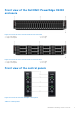


Table Of Contents
- Dell EMC PowerEdge C6400 Installation and Service Manual
- Dell EMC PowerEdge C6400 overview
- Installing and removing enclosure components
- Safety instructions
- Before working inside your system
- After working inside your system
- Recommended tools
- Dell EMC PowerEdge C6420 sled
- Drives
- Power supply units
- System cover
- Backplane cover
- Cooling fans
- Power interposer board
- Chassis management board
- Linking board
- Midplane
- Drive cage
- Backplanes and expander board
- Control panel
- Thermal sensor board
- Getting help
- Documentation resources

Front view of the Dell EMC PowerEdge C6400
enclosure
Figure 2. Front view of the enclosure with 24 x 2.5-inch drives
1. Left control panel 2. Drive bay
3. Right control panel 4. EST tag
Figure 3. Front view of the enclosure with 12 x 3.5-inch drives
1.
Left control panel 2. Drive bay
3. Right control panel 4. EST tag
Front view of the control panels
Figure 4. Front view of the left and right control panels
Table 2. Control panel
Dell EMC PowerEdge C6400 overview 7