
Owners Manual


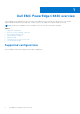
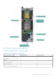


Table Of Contents
- Dell EMC PowerEdge C6420 Installation and Service Manual
- Dell EMC PowerEdge C6420 overview
- Initial system setup and configuration
- Installing and removing enclosure components
- Safety instructions
- Before working inside your system
- After working inside your system
- Recommended tools
- Dell EMC PowerEdge C6420 sled
- PERC battery
- Air shroud
- System memory
- Support bracket
- Linking board and PCIe cable
- Processor and heat sink module
- Removing a processor and heat sink module
- Installing a processor and heat sink module
- Removing the fabric processor from the processor heat sink module
- Installing the fabric processor into the processor heat sink module
- Removing the non-fabric processor from the processor and heat sink module
- Installing the non-fabric processor into a processor and heat sink module
- Removing the fabric and sideband cables
- Installing the fabric and sideband cables
- Expansion cards
- PCIe slot priority
- Removing the expansion card riser assembly
- Installing the expansion card riser assembly
- Removing an expansion card
- Installing an expansion card
- Removing the riser card
- Installing the riser card
- Removing the M.2 SATA x16 riser
- Installing the M.2 SATA x16 riser
- Removing the M.2 SATA card
- Installing the M.2 SATA card
- M.2 SSD module
- Mezzanine and OCP cards
- System battery
- System board
- Trusted Platform Module
- System diagnostics
- Jumpers and connectors
- Getting help
- Documentation resources

Table 2. Back panel features
Item Indicator, button, or
connector
Icon Description
Technical Specifications on
the product documentation
page.
8 iDRAC Direct micro USB port
Enables you to connect a
portable device to the sled.
9 OCP or OPA card slot N/A
Enables you to connect
Open Compute Project (OCP)
or Omni-Path Architecture
(OPA) expansion cards. For
more information, see the
Dell EMC PowerEdge C6420
Technical Specifications on
the product documentation
page.
10 EST pull out tab N/A This tab has the unique
Express Service Code,
Service Tag, and MAC
address labels.
11 System id indicator The System Identification(ID)
LED is available on the back
of the system. Press the
system ID button on the front
of the enclosure to identify a
system in a rack.
12 USB 3.0 port (2)
The USB ports are 9-pin and
3.0-compliant. These ports
enable you to connect USB
devices to the system.
Network ports indicator codes
Figure 3. LAN indicators on the QSFP OCP card
1. Link indicator
2. Activity indicator
Table 3. QSFP port on OCP card indicator codes
Dell EMC PowerEdge C6420 overview 9