Dell EMC PowerEdge C6420 Installations- und Service-Handbuch Vorschriftenmodell: E43S Series Vorschriftentyp: E43S001 April 2021 Rev.
Hinweise, Vorsichtshinweise und Warnungen ANMERKUNG: Eine ANMERKUNG macht auf wichtige Informationen aufmerksam, mit denen Sie Ihr Produkt besser einsetzen können. VORSICHT: Ein VORSICHTSHINWEIS warnt vor möglichen Beschädigungen der Hardware oder vor Datenverlust und zeigt, wie diese vermieden werden können. WARNUNG: Mit WARNUNG wird auf eine potenziell gefährliche Situation hingewiesen, die zu Sachschäden, Verletzungen oder zum Tod führen kann. © 2017 - 2021 Dell Inc. oder ihre Tochtergesellschaften.
Inhaltsverzeichnis Kapitel 1: Dell EMC PowerEdge C6420 – Überblick.............................................................................6 Unterstützte Konfigurationen.............................................................................................................................................. 6 Rückansicht des PowerEdge C6420-Schlittens................................................................................................................8 Anzeigecodes der Netzwerkports........
Prozessor und Kühlkörpermodul........................................................................................................................................39 Entfernen des Prozessor- und Kühlkörpermoduls.................................................................................................... 40 Installieren eines Prozessor- und Kühlkörpermoduls..................................................................................................
Kapitel 5: Jumper und Anschlüsse.................................................................................................. 87 Jumper-Einstellungen auf der Systemplatine.................................................................................................................. 87 Systemplatinenanschlüsse..................................................................................................................................................87 Deaktivieren vergessener Kennworte...........
1 Dell EMC PowerEdge C6420 – Überblick Der PowerEdge C6420-Einschub unterstützt bis zu zwei skalierbare Intel Xeon-Prozessoren mit 28 Cores pro Prozessor. Der Schlitten unterstützt auch dedizierte Mezzanine-, PCIe- und Open Compute Project (OCP)-Adapter für Erweiterung und Konnektivität. ANMERKUNG: Der skalierbare Intel Xeon-Prozessor mit Fabric-Anschluss wird auch als Native Omnipath bezeichnet.
Abbildung 1. Unterstützte Konfigurationen für PowerEdge C6420 Gehäusekonfiguration – Zusammenfassungstabelle Tabelle 1.
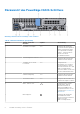
Rückansicht des PowerEdge C6420-Schlittens Abbildung 2. Rückansicht des PowerEdge C6420-Schlittens Tabelle 2. Rückseitenmerkmale (fortgesetzt) Element Anzeige, Taste oder Anschluss Symbol Beschreibung 1 Zusatzkarten-Steckplatz k. A. Ermöglicht das Anschließen von Zusatz-Erweiterungskarten. Weitere Informationen finden Sie in „Dell EMC PowerEdge C6420 – Technische Daten“ auf der Seite mit der Produktdokumentation. 2 Verschlussbügel des Schlittens k. A.
Tabelle 2. Rückseitenmerkmale Element Anzeige, Taste oder Anschluss Symbol Beschreibung Technische Daten“ auf der Seite mit der Produktdokumentation. 8 iDRAC Direct-Mikro-USBAnschluss 9 OCP- oder OPAKartensteckplatz k. A. Ermöglicht das Anschließen von Open Compute Project (OCP)- oder OmniPath Architecture (OPA)Erweiterungskarten. Weitere Informationen finden Sie in „Dell EMC PowerEdge C6420 – Technische Daten“ auf der Seite mit der Produktdokumentation. 10 EST-Schild zum Herausziehen k. A.
Tabelle 3.
Zuordnung von Einschüben zu Laufwerken Abbildung 5. Zuordnung von Einschüben zu Laufwerk für eine Konfiguration mit 24 x 2,5-Zoll-Laufwerken 1. Laufwerke 0–5 sind Einschub 1 zugeordnet 3. Laufwerke 12-17 sind Einschub 3 zugeordnet 5. Speicherort des (optionalen) NVMe-Laufwerks 2. Laufwerke 6-11 sind Einschub 2 zugeordnet 4. Laufwerke 18-23 sind Einschub 4 zugeordnet Abbildung 6. Zuordnung von Einschüben zu Laufwerk für eine Konfiguration mit 12 x 3,5-Zoll-Laufwerken 1.
● Bis zu 12 SAS/SATA-Geräte von Einschub 1 und Einschub 3 im Verzonungsmodus (12+12) ANMERKUNG: ● Installieren Sie Expander-Firmware 2.07 oder höher, um diese Konfigurationen zu unterstützen ● Der Expander-Modus ist nur mit einer PERC-Karte möglich und wird von integrierten SATA-Controllern nicht unterstützt.
Ausfindigmachen der Service-Tag-Nummer Ihres Systems Das System wird durch einen eindeutigen Express-Servicecode und eine eindeutige Service-Tag-Nummer identifiziert. Der ExpressServicecode und die Service-Tag-Nummer befinden sind auf der Rückseite des Einschubs durch Herausziehen der EST-Nummer ersichtlich. Mithilfe dieser Informationen kann Dell Support-Anrufe an den richtigen Mitarbeiter weiterleiten. Abbildung 7. Ausfindigmachen der Service-Tag-Nummer Ihres Systems 1.
Etikett mit Systeminformationen Informationen zur Systemplatine Abbildung 8.
Mechanische Übersicht Abbildung 9. Mechanische Übersicht Informationen zum Arbeitsspeicher Abbildung 10.
Jumper-Einstellungen Abbildung 11.
2 Anfängliche Systemeinrichtung und Erstkonfiguration Themen: • • • Einrichten des Systems iDRAC-Konfiguration Optionen zum Installieren des Betriebssystems Einrichten des Systems Führen Sie die folgenden Schritte aus, um das System einzurichten: Schritte 1. Packen Sie das Systemaus. 2. Installieren Sie das System im Rack. Weitere Informationen zum Einsetzen des Systems in das Rack finden Sie im Schieneninstallationshandbuch unter www.dell.com/poweredgemanuals. 3.
Schnittstellen Dokument/Abschnitt iDRAC Direct und Quick Sync 2 (optional) Siehe Benutzerhandbuch zum Integrated Dell Remote Access Controller unter www.dell.com/poweredgemanuals ANMERKUNG: Für den Zugriff auf iDRAC, stellen Sie sicher, dass Sie das Ethernet-Kabel an den dedizierten iDRAC9Netzwerkanschluss anschließen. Sie können auch den Zugriff auf iDRAC über das freigegebene LOM-Modus, wenn Sie sich dafür entschieden haben, wenn das System hat den freigegebenen LOM-Modus aktiviert.
Tabelle 6. Firmware und Treiber Methoden Speicherort Verwendung von Dell Repository Manager (DRM) www.dell.com/openmanagemanuals > Repository Manager Verwendung von Dell OpenManage Enterprise www.dell.com/openmanagemanuals > OpenManage Essentials Verwendung von Dell OpenManage Enterprise www.dell.com/openmanagemanuals > OpenManage Enterprise Verwendung von Dell Server Update Utility (SUU) www.dell.
3 Installieren und Entfernen von Gehäusekomponenten Themen: • • • • • • • • • • • • • • • • • Sicherheitshinweise Vor der Arbeit an Komponenten im Inneren Ihres Systems Nach der Arbeit an Komponenten im Inneren des Systems Empfohlene Werkzeuge Dell EMC PowerEdge C6420-Einschub PERC-Batterie Luftstromverkleidung Systemspeicher Stützhalterung Verbindungsplatine und PCIe-Kabel Prozessor und Kühlkörpermodul Erweiterungskarten M.
Vor der Arbeit an Komponenten im Inneren Ihres Systems Voraussetzungen Befolgen Sie die in Sicherheitshinweise. aufgelisteten Sicherheitshinweise. Schritte 1. Schalten Sie das System und alle angeschlossenen Peripheriegeräte aus. 2. Trennen Sie das System und die Peripheriegeräte von der Netzstromversorgung. Nach der Arbeit an Komponenten im Inneren des Systems Voraussetzungen Befolgen Sie die in Sicherheitshinweise. aufgelisteten Sicherheitshinweise. Schritte 1.
Abbildung 12. Richtlinien zur Installation des Schlittens Entfernen eines Schlittens Voraussetzungen 1. Befolgen Sie die in den Sicherheitshinweisen aufgeführten Sicherheitshinweise. ANMERKUNG: Informationen zur Optimierung der thermischen Leistung finden Sie unter Richtlinien zur Schlitteninstallation. ANMERKUNG: Das Verfahren zum Entfernen eines Schlittenplatzhalters und das zum Entfernen eines Schlittens ist identisch.
Abbildung 13. Entfernen eines Schlittens VORSICHT: Wenn Sie den Schlitten dauerhaft entfernen, installieren Sie umgehend einen Schlittenplatzhalter. Wird das Gehäuse für eine längere Zeit ohne einen Platzhalter betrieben, kann dies zu einer Überhitzung führen. Abbildung 14.
Nächste Schritte 1. Setzen Sie den Schlitten ein oder Setzen Sie einen Schlittenplatzhalter ein. Einbauen eines Schlittens Voraussetzungen 1. Befolgen Sie die Sicherheitshinweise unter Sicherheitshinweise. ANMERKUNG: Informationen zur optimierten thermischen Leistung finden Sie unter Richtlinien für die Installation von Schlitten. Schritte 1. Richten Sie den Schlitten horizontal am Gehäuse aus und setzen Sie den Schlitten in das Gehäuse ein. Abbildung 15.
Abbildung 16. Einsetzen eines Schlittenplatzhalters 2. Drücken Sie den blauen Verriegelungsriegel, um den Schlitten in das Gehäuse zu schieben. Achten Sie darauf, den Schlitten nicht vollständig einzuschieben, sodass hinten noch 20-30 mm Platz ist, wie in der Abbildung unten gezeigt. VORSICHT: Um etwaige Schäden an den Stiften am Schlitten zu vermeiden, wenden Sie beim Einsetzen des Schlittens in das Gehäuse keine übermäßige Kraft auf.
Abbildung 17. Achten Sie darauf, den Schlitten nicht vollständig einzuschieben, sodass hinten noch 20-30 mm Platz ist. 3. Schieben Sie den blauen Verriegelungsriegel vorsichtig nach unten, bis er einrastet. Nächste Schritte 1. Befolgen Sie die Anweisungen unter Nach der Arbeit an Komponenten im Inneren des Gehäuses. ANMERKUNG: Wenden Sie sich an den technischen Support von Dell, um die Servicekennung-Nummer der Systemplatine mit der Servicekennung-Nummer des physikalischen Knotens abzugleichen.
Abbildung 18. Entfernen der PERC-Batterie Nächste Schritte 1. Setzen Sie die PERC-Batterie ein. Einsetzen der PERC-Batterie Voraussetzungen 1. 2. 3. 4. Befolgen Sie die in Sicherheitshinweise. aufgelisteten Sicherheitshinweise. Befolgen Sie die Anweisungen unter Nach der Arbeit an Komponenten im Inneren Ihres Systems. Setzen Sie den Einschub in das Gehäuse ein. Schließen Sie gegebenenfalls das Batteriekabel der PERC-Karte an. Schritte 1.
Abbildung 19. Einsetzen der PERC-Batterie Nächste Schritte 1. Schließen Sie das Batteriekabel an die PERC-Karte an, falls es nicht verbunden ist. 2. Befolgen Sie die Anweisungen unter Nach der Arbeit an Komponenten im Inneren Ihres Systems. Luftstromverkleidung Entfernen des Kühlgehäuses Voraussetzungen 1. Befolgen Sie die in Sicherheitshinweise. aufgelisteten Sicherheitshinweise. 2. Befolgen Sie die Anweisungen unter Vor der Arbeit an Komponenten im Inneren Ihres Systems. 3.
Abbildung 20. Entfernen des Kühlgehäuses Nächste Schritte 1. Installieren Sie das Kühlgehäuse. Luftstromverkleidung einbauen Voraussetzungen 1. Befolgen Sie die in Sicherheitshinweise. aufgelisteten Sicherheitshinweise. Schritte 1. Setzen Sie das Kühlgehäuse in den Einschub ein. Richten Sie dabei das Scharnier des Kühlgehäuses auf den Steckplatz am Einschub aus.
Abbildung 21. Luftstromverkleidung einbauen Nächste Schritte 1. Schließen Sie das Batteriekabel an die PERC-Karte an, falls es nicht verbunden ist. 2. Befolgen Sie die Anweisungen unter Nach der Arbeit an Komponenten im Inneren Ihres Systems. Systemspeicher Richtlinien für Systemspeicher Das PowerEdge-System unterstützt DDR4-registrierte DIMMs (RDIMMs) und lastreduzierte DIMMs (LRDIMMs). Im Systemspeicher sind Anweisungen enthalten, die vom Prozessor ausgeführt werden.
Tabelle 7.
● Setzen Sie für maximale Leistung pro Prozessor jeweils sechs identische Speichermodule gleichzeitig ein (ein DIMM pro Kanal). Aktualisierung der DIMM-Bestückung im Modus „Performance Optimized“ (Leistungsoptimiert) bei vier bzw. acht DIMMs pro Prozessor: ● Sollen vier DIMMs pro Prozessor installiert werden, müssen die Steckplätze 1, 2, 4 und 5 bestückt werden. ● Sollen 8 DIMMs pro Prozessor installiert werden, müssen die Steckplätze 1, 2, 3, 4, 5, 6, 7 und 8 bestückt werden.
Optimierungsmodus Dieser Modus unterstützt SDDC (Single Device Data Correction) nur bei Speichermodulen mit x4-Gerätebreite. Es sind keine besonderen Vorgaben für die Steckplatzbestückung zu beachten. ● Zwei Prozessoren: Bestücken Sie die Steckplätze nach dem Rundlaufprinzip, beginnend mit Prozessor 1. ANMERKUNG: Prozessor 1 und Prozessor 2 sollten identisch sein. Tabelle 9.
3. Entfernen Sie das Kühlgehäuse. WARNUNG: Lassen Sie die Speichermodule ausreichend lange abkühlen nach dem Ausschalten des Systems. Fassen Sie Speichermodule an den Rändern an und vermeiden Sie den Kontakt mit Komponenten auf den Speichermodulen. VORSICHT: Um eine ordnungsgemäße Kühlung zu gewährleisten, müssen in allen nicht belegten Speichersockeln Speichermodulplatzhalter installiert werden. Entfernen Sie Speichermodulplatzhalter nur, wenn Sie in diesen Sockeln Speicher installieren möchten.
3. Richten Sie den Platinenstecker des Speichermoduls an der Passung im Speichermodulsockel aus und setzen Sie das Speichermodul in den Sockel ein. VORSICHT: Üben Sie keinen Druck auf die Mitte des Speichermoduls aus; üben Sie auf beide Enden des Speichermoduls einen gleichmäßigen Druck aus. ANMERKUNG: Die Passung im Speichermodulsockel sorgt dafür, dass die Speichermodule nicht verkehrt herum installiert werden können. 4.
Abbildung 25. Entfernen der Stützhalterung Nächste Schritte 1. Bauen Sie die Stützhalterung ein.. Einbauen der Stützhalterung Voraussetzungen 1. Befolgen Sie die in Sicherheitshinweise. aufgelisteten Sicherheitshinweise. Schritte 1. Setzen Sie die Stützhalterung in den Einschub. 2. Bringen Sie mit einem Kreuzschlitzschraubendreher (Größe 1) die Schrauben zur Befestigung der Halterung wieder an.
Abbildung 26. Einbauen der Stützhalterung Nächste Schritte 1. Installieren Sie den Einschub im Gehäuse. 2. Befolgen Sie die Anweisungen unter Nach der Arbeit an Komponenten im Inneren Ihres Systems. Verbindungsplatine und PCIe-Kabel Entfernen der Verbindungsplatine und der PCIe-Kabel Voraussetzungen ANMERKUNG: Merken Sie sich, wie das Kabel verlegt ist, wenn Sie es vom Schlitten entfernen. Sie müssen das Kabel später wieder korrekt verlegen, damit es nicht abgeklemmt oder gequetscht wird. 1. 2. 3. 4.
Abbildung 27. Entfernen der Verbindungsplatine und des SATA-Kabels Nächste Schritte 1. Bauen Sie die Verbindungsplatine und die PCIe-Kabel ein. Einbauen der Verbindungsplatine und der PCIe-Kabel Voraussetzungen ANMERKUNG: Merken Sie sich, wie das Kabel verlegt ist, wenn Sie es vom Schlitten entfernen. Sie müssen das Kabel später wieder korrekt verlegen, damit es nicht abgeklemmt oder gequetscht wird. 1. Befolgen Sie die in Sicherheitshinweise. aufgelisteten Sicherheitshinweise. Schritte 1.
Abbildung 28. Einbauen der Verbindungsplatine und des SATA-Kabels Nächste Schritte 1. Bauen Sie die Stützhalterung ein.. 2. Installieren Sie das Kühlgehäuse. 3. Befolgen Sie die Anweisungen unter Nach der Arbeit an Komponenten im Inneren Ihres Systems. Prozessor und Kühlkörpermodul VORSICHT: Dies ist eine vor Ort austauschbare Einheit (Field Replaceable Unit, FRU). Das Entfernen und die Installation der Einheit sollten nur von zertifizierten Dell Servicetechnikern durchgeführt werden.
Entfernen des Prozessor- und Kühlkörpermoduls Voraussetzungen WARNUNG: Der Kühlkörper fühlt sich nach dem Ausschalten des Systems möglicherweise noch eine Zeit lang heiß an. Lassen Sie den Kühlkörper einen Moment abkühlen, bevor Sie ihn entfernen. 1. 2. 3. 4. 5. Befolgen Sie die Sicherheitshinweise unter Sicherheitshinweise.. Befolgen Sie die Anweisungen unter Nach der Arbeit an Komponenten im Inneren Ihres Systems.. Entfernen Sie den Schlitten aus dem Gehäuse.. Entfernen Sie das Kühlgehäuse.
Abbildung 29. Entfernen des Prozessor- und Kühlkörpermoduls Nächste Schritte 1. Installieren Sie das Prozessor- und Kühlkörpermodul. Installieren eines Prozessor- und Kühlkörpermoduls Voraussetzungen VORSICHT: Nehmen Sie den Kühlkörper nur dann vom Prozessor ab, wenn Sie den Prozessor austauschen möchten. Der Kühlkörper verhindert eine Überhitzung des Prozessors. 1. Befolgen Sie die Sicherheitshinweise unter Sicherheitshinweise.. 2.
ANMERKUNG: Halten Sie das Prozessor-Kühlkörper-Modul parallel zur Systemplatine, um die Komponenten nicht zu beschädigen. 2. Drücken Sie die blauen Halteklammern nach innen, damit der Kühlkörper einrasten kann. 3. Ziehen Sie mit dem Torx-T30-Schraubendreher die Schrauben am Kühlkörper wie folgt in der angegebenen Reihenfolge an: a. Ziehen Sie die erste Schraube teilweise an (etwa drei Umdrehungen). b. Ziehen Sie die zweite Schraube vollständig an. c. Ziehen Sie die erste Schraube vollständig an.
3. Befolgen Sie die Anweisungen unter Nach der Arbeit an Komponenten im Inneren Ihres Systems. Entfernen des Fabric-Prozessors vom Prozessor-Kühlkörper-Modul Voraussetzungen WARNUNG: Kühlkörper sind auch nach dem Ausschalten des Systems eine Zeit lang zu heiß zum Anfassen. Lassen Sie den Kühlkörper einen Moment abkühlen, bevor Sie ihn entfernen. ANMERKUNG: Dieses Verfahren ist nur für den Austausch eines Kühlkörpers oder eines Prozessors bestimmt.
Abbildung 32. Entfernen der Prozessorhalterung Nächste Schritte 1. Installieren Sie den Fabric-Prozessor im Kühlkörpermodul des Prozessors. Installieren des Fabric-Prozessors im Prozessor-Kühlkörper-Modul Voraussetzungen ANMERKUNG: In einem Schlitten, der mit gemischten CPUs konfiguriert wurde, – ein Fabric-Prozessor im CPU2-Sockel und ein Fabric-Prozessor im CPU1-Sockel – müssen Sie die externen Omnipath-Linkkabel an Port 2 der OCP-Trägerkarte anschließen. Befolgen Sie die in Sicherheitshinweise.
Abbildung 33. Installieren der Prozessor-Halterung 4. Wenn Sie einen vorhandenen Kühlkörper verwenden, entfernen Sie die Wärmeleitpaste mit einem sauberen, fusselfreien Tuch vom Kühlkörper. VORSICHT: Wenn zu viel Wärmeleitpaste aufgetragen wird, kann die überschüssige Wärmeleitpaste in Kontakt mit dem Prozessorsockel kommen und diesen verunreinigen. 5. Verwenden Sie die im Prozessor-Kit enthaltene Spritze für die Wärmeleitpaste, um die Paste in einer dünnen Spirale oben auf den Prozessor aufzutragen.
Abbildung 34. Auftragen von Wärmeleitpaste auf der Oberseite des Prozessors 6. Setzen Sie den Kühlkörper auf den Prozessor und drücken Sie es nach unten, bis die Halterung auf den Kühlkörper einrastet. ANMERKUNG: ● Stellen Sie sicher, dass die beiden Löcher für Führungsstifte an Halterung mit Führungslöchern auf dem Kühlkörper übereinstimmen.
2. Befolgen Sie die Anweisungen unter Nach der Arbeit an Komponenten im Inneren Ihres Systems. Entfernen des Prozessors vom Modul des Prozessorkühlkörpers Voraussetzungen ANMERKUNG: Entfernen Sie den Prozessor nur dann vom Prozessor- und Kühlkörpermodul, wenn Sie den Prozessor oder den Kühlkörper austauschen. Beim Austausch einer Systemplatine ist dieses Verfahren nicht erforderlich. 1. 2. 3. 4. Befolgen Sie die Sicherheitshinweise unter Sicherheitshinweise..
Abbildung 37. Das Lösen der Prozessorhalterung Abbildung 38. Das Lösen der Prozessorhalterung 4. Heben Sie die Halterung und den Prozessor vom Kühlkörper, setzen Sie die Prozessor-Seite nach unten auf der Prozessor-Ablage. 5. Biegen Sie die äußeren Kanten der Halterung, um den Prozessor aus der Halterung zu lösen. ANMERKUNG: Stellen Sie sicher, dass der Prozessor und der Halterung sind in das Fach eingelegt nach dem Entfernen des Kühlkörpers.
Abbildung 39. Entfernen der Prozessorhalterung Nächste Schritte 1. Installieren Sie den Prozessor im Prozessor- und Kühlkörpermodul. 2. Installieren Sie den Nicht-Fabric-Prozessor im Prozessor-Kühlkörper-Modul.
Abbildung 40. Installieren der Prozessor-Halterung 3. Wenn Sie einen vorhandenen Kühlkörper verwenden, entfernen Sie die Wärmeleitpaste mit einem sauberen, fusselfreien Tuch vom Kühlkörper. 4. Verwenden Sie die im Prozessor-Kit enthaltene Spritze für die Wärmeleitpaste, um die Paste in einer dünnen Spirale oben auf den Prozessor aufzutragen. VORSICHT: Wenn zu viel Wärmeleitpaste aufgetragen wird, kann die überschüssige Wärmeleitpaste in Kontakt mit dem Prozessorsockel kommen und diesen verunreinigen.
ANMERKUNG: ● Stellen Sie sicher, dass die beiden Löcher für Führungsstifte an Halterung mit Führungslöchern auf dem Kühlkörper übereinstimmen. ● Drücken Sie nicht auf die Lamellen des Kühlkörpers. ● Stellen Sie sicher, dass Kontaktstift-1-Markierung auf dem Kühlkörper mit der Kontaktstift-1-Markierung auf der Halterung ausgerichtet ist (bevor Sie den Kühlkörper auf den Prozessor und Halterung legen). Abbildung 42. Setzen des Kühlkörpers auf den Prozessor ein Nächste Schritte 1.
1. Befolgen Sie die Sicherheitshinweise unter Sicherheitshinweise.. 2. Befolgen Sie die Anweisungen unter Vor der Arbeit an Komponenten im Inneren Ihres Systems.. 3. Entfernen Sie das Kühlgehäuse. Schritte 1. Ziehen Sie die blaue Zuglasche am Sperrriegel nach oben, um den Stecker aus dem Anschluss auf der Prozessorträgerplatte zu lösen. 2. Zum Lösen des Fabric-Anschlusses ziehen Sie den Anschluss vom Prozessor ab. 3.
Abbildung 44. Einbauen der Fabric- und Seitenbandkabel Nächste Schritte 1. Installieren Sie das Kühlgehäuse. 2. Befolgen Sie die Anweisungen unter Nach der Arbeit an Komponenten im Inneren Ihres Systems. Erweiterungskarten ANMERKUNG: Bei einem fehlenden oder nicht unterstützten Erweiterungskarten-Riser wird ein System Event Log (SEL)-Ereignis protokolliert. Dies verhindert nicht das Einschalten des Systems und keine BIOS-, POST-Meldungen oder F1/F2-Pausen werden angezeigt.
Tabelle 11. Unterstützte Erweiterungsoptionen Riser Steckplatzn Bauweise ummer Steuern des Prozessors Elektrische Bandbreite des Steckplatzes/Hardwareanschluss Stromvers orgung OCPZusatzkartensteckpl atz (Steckplatz 3) 1 Prozessor 1 SKL-F OCP-Zusatzkarte belegt durch SKL-F-QSFP-Trägerkarte 25 W Zusatzkarte ANMERKUNG: Die Daten für den Erweiterungsbus finden Sie in den technischen Daten für PowerEdge C6420 unter www.dell.com/poweredgemanuals . Tabelle 12.
Tabelle 12.
Tabelle 12. Unterstützte Erweiterungskarten Kartentyp Bauweise Verbindu ngsband breite Steckplatz Maximale Anzahl an Karten priorität SATA-M.2-Karte (x8) k. A. X8 PCIe Adapter (PCIe-Bus reserviert für ESI) SATA-M.2-Karte (x16) k. A.
Installieren der Baugruppe des Erweiterungskarten-Risers Voraussetzungen ANMERKUNG: Sie müssen über leeren Erweiterungssteckplätzen Erweiterungskarten-Abdeckbleche installieren, um die FCC (Federal Communications Commission)-Zertifizierung des Systems aufrechtzuerhalten. Die Abdeckungen halten auch Staub und Schmutz vom System fern und helfen, die korrekte Kühlung und den Luftstrom innerhalb des Systems aufrechtzuerhalten. 1. Befolgen Sie die Sicherheitshinweise unter Sicherheitshinweise.. Schritte 1.
Abbildung 47. Entfernen einer Erweiterungskarte Abbildung 48. Einbauen des Erweiterungskarten-Abdeckblechs Nächste Schritte Setzen Sie die Erweiterungskarte ein oder Bauen Sie das Erweiterungskarten-Abdeckblech ein.
Installieren einer Erweiterungskarte Voraussetzungen VORSICHT: Erweiterungskarten dürfen nur in die Steckplätze auf dem Erweiterungskarten-Riser eingesetzt werden. Versuchen Sie nicht, Erweiterungskarten direkt in den Riser-Anschluss auf der Systemplatine zu stecken. 1. Befolgen Sie die in Sicherheitshinweise. aufgelisteten Sicherheitshinweise. 2. Nehmen Sie die Erweiterungskarte aus der Verpackung und bereiten Sie sie für den Einbau vor.
Abbildung 50. Installieren einer Erweiterungskarte Nächste Schritte 1. Installieren Sie die Baugruppe des Erweiterungskarten-Risers.. 2. Befolgen Sie die Anweisungen unter Nach der Arbeit an Komponenten im Inneren Ihres Systems. Entfernen der Riserkarte Voraussetzungen 1. 2. 3. 4. Befolgen Sie die Sicherheitshinweise unter Sicherheitshinweise.. Befolgen Sie die Anweisungen unter Vor der Arbeit an Komponenten im Inneren Ihres Systems.. Entfernen Sie die Baugruppe des Erweiterungskarten-Risers..
Abbildung 51. Entfernen der Riserkarte Nächste Schritte 1. Setzen Sie die Riser-Karte ein. Einsetzen der Riserkarte Voraussetzungen 1. Befolgen Sie die in Sicherheitshinweise. aufgelisteten Sicherheitshinweise. Schritte 1. Setzen Sie die Riserkarte in die Erweiterungskartenhalterung. 2. Ziehen Sie mit einem Kreuzschlitzschraubendreher (Größe 2) die Schrauben zur Befestigung der Riser-Karte an der Erweiterungskartenhalterung an.
Abbildung 52. Einsetzen der Riserkarte Nächste Schritte 1. Setzen Sie die Erweiterungskarte ein, falls sie entfernt wurde. 2. Installieren Sie die Baugruppe des Erweiterungskarten-Risers.. 3. Befolgen Sie die Anweisungen unter Nach der Arbeit an Komponenten im Inneren Ihres Systems. Entfernen des M.2-SATA-Risers (x16) Voraussetzungen 1. Befolgen Sie die Sicherheitshinweise unter Sicherheitshinweise.. 2. Befolgen Sie die Anweisungen unter Vor der Arbeit an Komponenten im Inneren Ihres Systems.. Schritte 1.
Abbildung 53. Entfernen des M.2-SATA-Risers (x16) Nächste Schritte 1. Setzen Sie den M.2-SATA-Riser (x16) ein. Einsetzen des M.2-SATA-Risers (x16) Voraussetzungen 1. Befolgen Sie die in Sicherheitshinweise. aufgelisteten Sicherheitshinweise. Schritte 1. Schließen Sie das Datenkabel am Riser an. 2. Setzen Sie das passgeformte Ende des M.2-SATA-Risers in den Anschluss auf der Systemplatine. 3. Richten Sie den Platinenstecker aus und setzen Sie ihn in den Anschluss auf der Systemplatine. 4.
Abbildung 54. Einsetzen des M.2-SATA-Risers (x16) Nächste Schritte 1. Befolgen Sie die Anweisungen unter Nach der Arbeit an Komponenten im Inneren Ihres Systems. Entfernen der M.2-SATA-Karte Voraussetzungen 1. 2. 3. 4. Befolgen Sie die Sicherheitshinweise unter Sicherheitshinweise.. Befolgen Sie die Anweisungen unter Vor der Arbeit an Komponenten im Inneren Ihres Systems.. Entfernen Sie die Baugruppe des Erweiterungskarten-Risers, falls zutreffend. Entfernen Sie den M.2-Riser (x16) oder setzen Sie die M.
Abbildung 55. Entfernen der M.2-SATA-Karte vom M.2-SATA-Riser (x16) Abbildung 56. Entfernen der M.2-SATA-Karte von der Zusatzkarte (x8) Nächste Schritte 1. Setzen Sie die M.2-SATA-Karte ein . Einsetzen der M.2-SATA-Karte Voraussetzungen 1. Befolgen Sie die in Sicherheitshinweise. aufgelisteten Sicherheitshinweise. Schritte 1. Setzen Sie den Platinenstecker der M.2-SATA-Karte in den Anschluss auf der Platine und drücken Sie die Karte hinein. 2.
Abbildung 57. Einsetzen der M.2-SATA-Karte über dem SATA-Riser (x16) Abbildung 58. Einsetzen der M.2-SATA-Karte über der SATA-Zusatzkarte (x8) Nächste Schritte 1. Falls zuvor entfernt, installieren Sie die Baugruppe des PCIe-Erweiterungskarten-Risers.. 2. Setzen Sie den M.2-Riser (x16) oder setzen Sie die M.2-Zusatzkarte (x8) ein. ANMERKUNG: Das Verfahren zum Einsetzen der M.2-SATA-Zusatzkarte (x8) ist ähnlich wie das beim Einsetzen einer Zusatzkarte. 3.
Entfernen des M.2-SATA-Risers (x16) Voraussetzungen 1. Befolgen Sie die Sicherheitshinweise unter Sicherheitshinweise.. 2. Befolgen Sie die Anweisungen unter Vor der Arbeit an Komponenten im Inneren Ihres Systems.. 3. Entfernen Sie den Schlitten aus dem Gehäuse.. Schritte 1. Lösen Sie mit einem Kreuzschlitzschraubenzieher (Nr. 1) die Schraube, mit der der Riser am Schlitten befestigt ist. 2. Heben Sie den Riser an, um ihn aus dem Anschluss auf der Systemplatine zu lösen. 3.
Abbildung 60. Einsetzen des M.2-SATA-Risers (x16) Nächste Schritte 1. Installieren Sie den Einschub im Gehäuse. 2. Befolgen Sie die Anweisungen unter Nach der Arbeit an Komponenten im Inneren Ihres Systems. Entfernen der M.2-SATA-Karte Voraussetzungen 1. 2. 3. 4. 5. Befolgen Sie die Sicherheitshinweise unter Sicherheitshinweise.. Befolgen Sie die Anweisungen unter Vor der Arbeit an Komponenten im Inneren Ihres Systems.. Entfernen Sie den Schlitten aus dem Gehäuse..
Abbildung 61. Entfernen der M.2-SATA-Karte vom M.2-SATA-Riser (x16) Abbildung 62. Entfernen der M.2-SATA-Karte von der Zusatzkarte (x8) Nächste Schritte Setzen Sie die M.2-SATA-Karte ein. Einsetzen der M.2-SATA-Karte Voraussetzungen 1. Befolgen Sie die in Sicherheitshinweise. aufgelisteten Sicherheitshinweise. Schritte 1. Setzen Sie den Platinenstecker der M.2-SATA-Karte in den Anschluss auf der Platine und drücken Sie die Karte hinein. 2.
Abbildung 63. Einsetzen der M.2-SATA-Karte über dem SATA-Riser (x16) Abbildung 64. Einsetzen der M.2-SATA-Karte über der SATA-Zusatzkarte (x8) Nächste Schritte 1. Falls zuvor entfernt, installieren Sie die Baugruppe des PCIe-Erweiterungskarten-Risers.. 2. Bauen Sie den M.2-Riser (x16) oder die M.2-Zusatzkarte (x8) ein. ANMERKUNG: Das Verfahren zum Einbauen der M.2-SATA-Zusatzkarte (x8) ist ähnlich wie das beim Entfernen einer Zusatzkarte. 3. Installieren Sie den Einschub im Gehäuse. 4.
Zusatz- und OCP-Karten Entfernen einer Mezzaninekarte Voraussetzungen ANMERKUNG: Das Verfahren zum Entfernen des Zusatzkarten-Platzhalters ist ähnlich wie das zum Entfernen einer Zusatzkarte. 1. Befolgen Sie die Sicherheitshinweise unter Sicherheitshinweise.. 2. Befolgen Sie die Anweisungen unter Vor der Arbeit an Komponenten im Inneren Ihres Systems.. 3. Entfernen Sie die Baugruppe des Erweiterungskarten-Risers.. Schritte 1.
Abbildung 65. Entfernen einer Mezzaninekarte Nächste Schritte 1. Bauen Sie die Zusatzkarte ein oder Bauen Sie das Abdeckblech der Zusatzkarte ein. Installieren einer Mezzaninekarte Voraussetzungen ANMERKUNG: Das Verfahren zum Einsetzen des Zusatzkarten-Platzhalters ähnelt dem Verfahren zum Entfernen einer Zusatzkarte. 1. Befolgen Sie die in Sicherheitshinweise. aufgelisteten Sicherheitshinweise. Schritte 1. Verbinden und befestigen Sie die Zusatzkartenhalterung an der Zusatzkarte. 2.
3. Drücken Sie den Rand-Anschluss der Karte und drücken Sie die Karte fest, bis die Karte vollständig auf der Brücken-Platine eingesetzt ist. 4. Befestigen Sie die Baugruppe der Zusatzkarte und Halterung unter Verwendung eines Kreuzschlitzschraubendrehers (Größe 2) mit Schrauben am Einschub. Abbildung 66. Installieren einer Mezzaninekarte Nächste Schritte 1. Bauen Sie die Zusatzkarte ein oder Bauen Sie das Abdeckblech der Zusatzkarte ein. 2. Bauen Sie die Baugruppe des Erweiterungskarten-Risers ein. 3.
4. Entfernen Sie die Zusatzkarte.. Schritte Ziehen Sie die Zusatzkarten-Brückenplatine aus dem Zusatzkarten-Steckplatz auf der Systemplatine. Abbildung 67. Zusatzkarten-Brückenplatine entfernen Nächste Schritte 1. Setzen Sie die Zusatzkarten-Brückenplatine ein.. Einsetzen der Zusatzkarten-Brückenplatine Voraussetzungen 1. Befolgen Sie die in Sicherheitshinweise. aufgelisteten Sicherheitshinweise. Schritte Setzen Sie die Zusatzkarten-Brückenplatine in den Zusatzkarten-Steckplatz auf der Systemplatine ein.
Abbildung 68. Einsetzen der Zusatzkarten-Brückenplatine Nächste Schritte 1. Setzen Sie die Zusatzkarte ein. 2. Installieren Sie die Baugruppe des Erweiterungskarten-Risers.. 3. Befolgen Sie die Anweisungen unter Nach der Arbeit an Komponenten im Inneren Ihres Systems. Entfernen der OCP-Karte Voraussetzungen ANMERKUNG: Das Verfahren zum Entfernen des Zusatzkarten-Platzhalters ist ähnlich wie das zum Entfernen einer Zusatzkarte. 1. Befolgen Sie die Sicherheitshinweise unter Sicherheitshinweise.. 2.
Abbildung 69. Entfernen der OCP-Karte Nächste Schritte 1. Installieren Sie die OCP-Karte. Installieren der OCP-Karte Voraussetzungen 1. Befolgen Sie die in Sicherheitshinweise. aufgelisteten Sicherheitshinweise. Schritte 1. Setzen Sie die Open Compute Project (OCP)-Karte in den Schlitten. Richten Sie dabei den Anschluss der Karte mit dem Anschluss der Systemplatine aus. 2. Sie müssen außerdem die Löcher auf der Karte an den Führungsstiften an den blauen Halteklammern ausrichten. 3.
Abbildung 70. Installieren der OCP-Karte Nächste Schritte 1. Setzen Sie die Zusatzkarte ein. 2. Befolgen Sie die Anweisungen unter Nach der Arbeit an Komponenten im Inneren Ihres Systems. Systembatterie Austauschen der Systembatterie Voraussetzungen WARNUNG: Bei falschem Einbau einer neuen Batterie besteht Explosionsgefahr. Tauschen Sie die Batterie nur gegen eine Batterie desselben oder eines gleichwertigen, vom Hersteller empfohlenen Typs aus.
Abbildung 71. Entfernen der Systembatterie Nächste Schritte 1. Installieren Sie die Systembatterie. Installieren der Systembatterie Voraussetzungen WARNUNG: Bei falschem Einbau einer neuen Batterie besteht Explosionsgefahr. Tauschen Sie die Batterie nur gegen eine Batterie desselben oder eines gleichwertigen, vom Hersteller empfohlenen Typs aus. Weitere Informationen finden Sie in den Sicherheitshinweisen, die mit Ihrem System geliefert wurden. ANMERKUNG: Der Akku ist eine vor Ort austauschbare Einheit.
Abbildung 72. Installieren der Systembatterie Nächste Schritte 1. Installieren Sie den Erweiterungskarten-Riser, falls dieser entfernt wurde. 2. Befolgen Sie die Anweisungen unter Nach der Arbeit an Komponenten im Inneren Ihres Systems. 3. Drücken Sie beim Start die Taste , um das System-Setup aufzurufen und stellen Sie sicher, dass die Batterie ordnungsgemäß funktioniert. 4. Geben Sie im System-Setup in den Feldern Uhrzeit und Datum das richtige Datum und die richtige Uhrzeit ein. 5.
2. Fassen Sie die Systemplatine an den Rändern und heben Sie sie aus dem Schlitten heraus. Abbildung 73. Entfernen der Systemplatine Nächste Schritte 1. Bauen Sie die Systemplatine ein. Installieren der Systemplatine Voraussetzungen Befolgen Sie die in den Sicherheitshinweisen aufgeführten Sicherheitshinweise.
Abbildung 74. Installieren der Systemplatine Nächste Schritte 1. Falls das Trusted Platform Module (TPM) nicht installiert wurde, setzen Sie es ein. Informationen zur Installation des TPM finden Sie im Abschnitt „Installing the Trusted Platform Module“ (Installieren des Trusted Platform Module). Weitere Informationen zum TPM finden Sie im Abschnitt „Trusted Platform Module“. ANMERKUNG: Ist das TPM-Steckmodul einmal installiert, ist es mit der Hauptplatine verbunden und kann nicht mehr entfernt werden.
werden automatisch auf einem Flash-Sicherungsgerät und einer rSPI-Karte gesichert. Wenn das BIOS eine neue Systemplatine und den Service-Tag auf der rSPI-Karte im Flash-Sicherungsgerät erkennt, fordert das BIOS den Benutzer dazu auf, die Sicherungsinformationen wiederherzustellen. Info über diese Aufgabe ANMERKUNG: Riser1 muss installiert werden, um die Easy Restore-Funktion zu aktivieren. Schritte 1. Schalten Sie das System ein.
2. Befolgen Sie die Anweisungen unter Vor der Arbeit an Komponenten im Inneren Ihres Systems. ANMERKUNG: ● Stellen Sie sicher, dass Ihr Betriebssystem die Version des installierten Trusted Platform Modul unterstützt. ● Stellen Sie sicher, dass Sie die aktuelle Firmware heruntergeladen und in Ihrem System installiert haben. ● Stellen Sie sicher, dass das BIOS so konfiguriert ist, dass der UEFI-Boot-Modus aktiviert ist.
Nächste Schritte 1. Bauen Sie die Systemplatine ein. 2. Befolgen Sie die Anweisungen unter Nach der Arbeit an Komponenten im Inneren Ihres Systems. Initialisieren des TPM für BitLocker-Benutzer Schritte Initialisieren Sie das TPM. Weitere Informationen finden Sie unter Initialisieren des TPM für Intel TXT-Benutzer. Die TPM Status (TPM-Status) ändert sich zu Enabled (Aktiviert). Initialisieren des TPM 1.2 für TXT-Benutzer Schritte 1. Drücken Sie beim Start des System F2, um das System-Setup aufzurufen. 2.
4 System--Diagnose Führen Sie bei Störungen der System die System-Diagnose durch, bevor Sie Dell zwecks technischer Unterstützung kontaktieren. Der Zweck der System-Diagnose ist es, die Hardware der System ohne zusätzliche Ausrüstung und ohne das Risiko von Datenverlust zu testen. Wenn Sie ein Problem nicht selbst beheben können, können Service- und Supportmitarbeiter die Diagnoseergebnisse zur Lösung des Problems verwenden.
System- Diagnose-Steuerelemente Menü Beschreibung Konfiguration Zeigt die Konfigurations- und Statusinformationen für alle erkannten Geräte an. Results (Ergebnisse) Zeigt die Ergebnisse aller durchgeführten Tests an. System- Zustand Liefert eine aktuelle Übersicht über die System-Leistung. Ereignisprotokoll Zeigt ein Protokoll der Ergebnisse aller Tests, die auf dem System durchgeführt wurden, und die dazugehörigen Zeitstempel an.
5 Jumper und Anschlüsse Dieses Thema enthält spezifische Informationen über die Jumper. Außerdem finden Sie hier einige grundlegende Informationen zu Jumpern und Switches und die Anschlüsse auf den verschiedenen Platinen im System. Mit den Jumpern auf der Systemplatine können System- und Setup-Kennwörter deaktiviert werden. Sie müssen die Anschlüsse auf der Systemplatine kennen, um Komponenten und Kabel korrekt zu installieren.
Tabelle 13.
6 Wie Sie Hilfe bekommen Themen: • • • • • Kontaktaufnahme mit Dell EMC Feedback zur Dokumentation Zugriff auf Systeminformationen mithilfe von QRL Automatische Unterstützung mit SupportAssist Informationen zum Recycling oder End-of-Life-Service Kontaktaufnahme mit Dell EMC Dell EMC bietet verschiedene Optionen für Online- und Telefonsupport an.
● Referenzmaterialien, darunter Installations- und Service-Handbuch, und mechanische Übersicht ● Ihre Service-Tag-Nummer für einen schnellen Zugriff auf Ihre Hardware-Konfiguration und Garantieinformationen ● Eine direkte Verbindung zu Dell für die Kontaktaufnahme mit dem technischen Support und den Vertriebsteams Schritte 1. Rufen Sie www.dell.com/qrl auf und navigieren Sie zu Ihrem spezifischen Produkt oder 2. Verwenden Sie Ihr Smartphone bzw.
7 Dokumentationsangebot In diesem Abschnitt finden Sie Informationen zum Dokumentationsangebot für Ihre PowerEdgeC6420System. So zeigen Sie das Dokument an, dass in der Tabelle der Dokumentationsressourcen aufgeführt ist: ● Über die Dell EMC Support-Website: 1. Klicken Sie auf den Dokumentations-Link in der Spalte Standort der Tabelle. 2. Klicken Sie auf das benötigte Produkt oder die Produktversion. ANMERKUNG: Den Produktnamen und das Modell finden Sie auf der Vorderseite Ihrer System. 3.
Tabelle 14. Dokumentationsangebot (fortgesetzt) Task Dokument Speicherort Um die auf Ihrer System vorhandene Version von iDRAC zu identifizieren, klicken Sie in der iDRAC-Weboberfläche auf ?. > About. Informationen über das Installieren des Betriebssystems finden Sie in der Dokumentation zum Betriebssystem. https://www.dell.com/ operatingsystemmanuals Verwalten Ihrer System https:// Weitere Informationen zur Systemewww.dell.
Tabelle 14. Dokumentationsangebot Task Dokument Speicherort Arbeiten mit Dell PowerEdge RAIDController Weitere Informationen zum Verständnis der Funktionen der Dell PowerEdge RAID-Controller (PERC), Software RAIDController, BOSS-Karte und Bereitstellung der Karten finden Sie in der Dokumentation zum Speicher-Controller. www.dell.