
Reference Guide

212 | Stacking
www.dell.com | support.dell.com
Verifying a Stack Configuration
Using LEDs
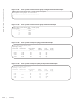
Table 17-2 lists the status of a stacked switch according to the color of the System Status light emitting
diodes (LEDs) on its front panel.
Using Show Commands
To display information on the stack configuration, use the show commands in Table 17-3 on the master
switch.
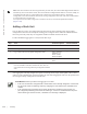
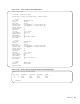
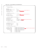
Figure 17-18. show system brief Command Example
Table 17-2. System Status LED on a Stacked Switch
Color Meaning
Blue The switch is operating as the stack master or as a standalone unit.
Off The switch is a member or standby unit.
Amber The switch is booting or a failure condition has occurred.
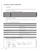
Table 17-3. Displaying Stack Configurations
Command Output
show system [brief] (Figure 17-18 and Figure 17-19) Displays stacking roles (master, standby, and member units) and
the stack MAC address.
show inventory optional-module (Figure 17-20) Displays the FlexIO modules currently installed in expansion
slots 0 and 1 on a switch and the expected module logically
provisioned for the slot.
show system stack-unit unit-number stack-group
configured
(Figure 17-21)
Displays the stack groups allocated on a stacked switch. Valid
stack-unit numbers: 0 or 1.
show system stack-unit unit-number stack-group
(Figure 17-22)
Displays the port numbers that correspond to the stack groups on
a switch. Valid stack-unit numbers: 0 or 1.
show system stack-ports [status | topology]
(Figure 17-23)
Displays the type of stack topology (ring or daisy chain) with a
list of all stacked ports, port status, link speed, and peer stack-unit
connection.
FTOS# show system brief
StStack MAC : 00:1e:c9:f1:00:9b
-- Stack Info --
Unit UnitType Status ReqTyp CurTyp Version Ports
------------------------------------------------------------------------------------
0 Management online I/O-Aggregator I/O-Aggregator 8-3-17-46 56
1 Standby online I/O-Aggregator I/O-Aggregator 8-3-17-46 56
2 Member not present
3 Member not present
4 Member not present
5 Member not present