Third party information brought to you courtesy of Dell. SwitchX 56Gb/s InfiniBand Blade Switch I/O Module for PowerEdge M-Series User Manual PN: M4001F, M4001Q Rev 1.0 www.mellanox.
Rev 1.0 NOTE: THIS HARDWARE, SOFTWARE OR TEST SUITE PRODUCT (“PRODUCT(S)”) AND ITS RELATED DOCUMENTATION ARE PROVIDED BY MELLANOX TECHNOLOGIES “AS-IS” WITH ALL FAULTS OF ANY KIND AND SOLELY FOR THE PURPOSE OF AIDING THE CUSTOMER IN TESTING APPLICATIONS THAT USE THE PRODUCTS IN DESIGNATED SOLUTIONS. THE CUSTOMER'S MANUFACTURING TEST ENVIRONMENT HAS NOT MET THE STANDARDS SET BY MELLANOX TECHNOLOGIES TO FULLY QUALIFY THE PRODUCTO(S) AND/OR THE SYSTEM USING IT.
InfiniBand Blade Switch I/O Module for PowerEdge M-Series Rev 1.0 Contents Contents 3 Revision History 4 About this Manual 5 Chapter 1 7 Chapter 2 Chapter 3 Chapter 4 Overview 1.1 InfiniBand Connectors 1.2 Switch Status Lights 1.3 I2C Interface RJ-45 Connector 8 9 10 Installation and Basic Operation 11 2.1 Installation Safety Warnings 2.2 Mechanical Installation 2.2.1 Removing an Old Switch From the Chassis 2.2.2 Removing an I/O Module Blank From the Chassis 2.2.
Rev 1.0 Revision History Table 1 - Revision History Table Date Revision Description November 2011 1.
InfiniBand Blade Switch I/O Module for PowerEdge M-Series Rev 1.0 About this Manual This manual describes the installation and basic use of the SwitchX M4001F 56 Gb/s, and the M4001Q 40 Gb/s InfiniBand blade switch I/O modules for the PowerEdge M-Series chassis. Intended Audience This manual is intended for users and system administrators responsible for installing and setting up the switch platforms listed above. The manual assumes familiarity with the InfiniBand® Architecture Specification.
Rev 1.0 This symbol indicates information that is helpful to the user. This symbol indicates a situation that can potentially cause damage to hardware or software. BEWARE! This symbol indicates a situation that can potentially cause personal injury or damage to hardware or software.
InfiniBand Blade Switch I/O Module for PowerEdge M-Series 1 Rev 1.0 Overview The SwitchX M4001F 56 Gb/s, and the M4001Q 40 Gb/s InfiniBand blade switch I/O module for the PowerEdge M-Series chassis provides a high bandwidth, low latency fabric for Enterprise Data Centers (EDC), High-Performance Computing (HPC), and Embedded environments. Based on the 5th generation InfiniBand switch device (1st Generation SwitchX).
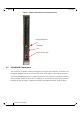
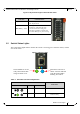
Rev 1.0 Overview Figure 1: Switch Front Panel and Locking Mechanism Locking Mechanism Port LEDs Switch Status Lights 1.1 InfiniBand Connectors This switch has 16 QSFP connectors through the front panel. The remaining 16 interfaces are through the Midplane Connector out of the back of the switch. Figure 1 shows the front 16 ports. Each of the InfiniBand ports has two LEDs located between the connectors and the I2C interface.
InfiniBand Blade Switch I/O Module for PowerEdge M-Series Rev 1.0 Figure 2: Physical and Logical Link Indication LEDs LED Name Connection Status Physical Link - Green Off – No Physical Link ON – Physical Link Blinking – indicates Data Transfer Constant on – indicates Link exists with no Data Transfer taking place Off with green LED lit – indicates that the Subnet Manager may not be running Data Activity - Yellow 1.
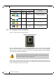
Rev 1.0 Overview LED Switch Status Indication Green Status ON BLINKING BLUE The CMC is identifying the newly installed switch ON ON BLUE Switch is on and operating Normally ON ON or BLINKING AMBER Fault in System Self-diagnosed OFF ON or BLINKING AMBER Fault in System CMC-detected Blinking Blue 1.3 I2C Interface RJ-45 Connector There is an “I2C”interface on the front panel. Figure 4: I2C RJ-45 Interface The I2C connection provides access to Flash and EEPROMs.
InfiniBand Blade Switch I/O Module for PowerEdge M-Series 2 Rev 1.0 Installation and Basic Operation Installation and initialization of the I/O module are straightforward processes, requiring attention to the normal mechanical, power, and thermal precautions for rack-mounted equipment.
Rev 1.0 Installation and Basic Operation 5. Copper InfiniBand Cable Connecting/Disconnecting Copper InfiniBand cables are heavy and not flexible, as such they should be carefully attached to or detached from the connectors. Support the cable’s weight using the rack and a cable management system. Refer to the cable manufacturer for special warnings and instructions. 6.
InfiniBand Blade Switch I/O Module for PowerEdge M-Series 2.2 Rev 1.0 Mechanical Installation These switches are hot pluggable. It is not necessary to power down the Dell Chassis to install a new switch or to replace an old switch with a new one. Figure 5: Rear View of the Dell PowerEdge M1000e Chassis Latch Release Buttons Locking Arms A1 B1 C1 Channel 1 slots C2 B2 A2 Channel 2 slots M4001[F, Q] blades are not allowed in the Fabric A slots.
Rev 1.0 Installation and Basic Operation 2.2.2 Removing an I/O Module Blank From the Chassis 1. 2. 3. Unlock the I/O Module Blank by pushing the red latch release button. Pull the locking arm down to a position perpendicular to the front of the chassis. Pull the I/O Module Blank out of the chassis using the locking arm. 2.2.3 Installing the Mellanox M4001[F, Q] Switch Into the Dell Chassis Make sure the rack is stable on a solid floor and that the rack is filled from the bottom up.
InfiniBand Blade Switch I/O Module for PowerEdge M-Series Rev 1.0 To remove, disengage the locks and slowly pull the connector away from the port receptacle. Both LED indicators will turn off when the cable is unseated. Care should be taken not to impede the air exhaust flow through the chassis. Cable lengths should be used which allow for routing horizontally around to the side of the chassis before bending upward or downward in the rack.
Rev 1.0 Cluster Management and Firmware 3 Cluster Management and Firmware 3.1 Network Management and Clustering Software Download and install, on all nodes, the Mellanox OpenFabric software package for Linux, Windows, or other operating systems from the Mellanox software website: http://www.mellanox.com >Downloads > InfiniBand SW/Drivers.
InfiniBand Blade Switch I/O Module for PowerEdge M-Series 4 Rev 1.0 Troubleshooting As soon as a switch is inserted in make sure that the power LED comes on. The power LED for the switch does not come on: 1. 2. Check that the chassis has power. Remove and reinstall the switch. The status LED for the switch is blinking amber: 1. 2. Remove the switch from the chassis and re-insert it (verify that the switch is all the way in the chassis and the lever is firmly closed).
Rev 1.0 Appendix A: Specifications Table 4 - M4001[F, Q] Specification Data Physical Power and Environmental H x W x D: 12.2 x 1.34 x 10.7 inches 310.7 x 34.1 x 271.8 mm Weight: 2.6Kg fully configured Mounting: Vertically mounted rack SerDes Speeds 10, 20, 40, 56 Gb/s per port Connectors: QSFP 16 external QSFP connectors 16 internal backplane connectors Typ Power: FDR Passive: 80.66W or 275.22BTUs/hr Active: 108.26W or 369.40BTUs/hr QDR Passive: 60.42W or 206.16BTUs/hr Active: 88.02W or 300.
InfiniBand Blade Switch I/O Module for PowerEdge M-Series Physical Rev 1.0 Power and Environmental Scalability and Performance Switching Performance: Simultaneous wire-speed any port to any port Addressing: 48K Unicast Addresses Max. per Subnet 16K Multicast Addresses per Subnet Switching Capacity 2.
Rev 1.
InfiniBand Blade Switch I/O Module for PowerEdge M-Series Rev 1.0 Appendix B.1: FCC Statements (USA) Class A Statements: § 15.21 Statement Warning! Changes or modifications to this equipment not expressly approved by the party responsible for compliance (Mellanox Technologies) could void the user's authority to operate the equipment. §15.105(a) Statement NOTE: This equipment has been tested and found to comply with the limits for a Class A digital device, pursuant to Part 15 of the FCC Rules.
Rev 1.0 (Translation - "This is a Class A product based on the standard of the Voluntary Control Council for Interference by Information Technology Equipment (VCCI). If this equipment is used in a domestic environment, radio interference may occur, in which case the user may be required to take corrective actions.") B.1.4 MIC Certification (Korea) Korea's "Regulation for Certification of Information and Communication Equipment," requires EMC testing and certification for many electronic products.
InfiniBand Blade Switch I/O Module for PowerEdge M-Series Rev 1.
7 8 11 1 0 9 12 13 14 15 16 17 18 19 ModSelL ResetL SCL SDA GND RX3p RX3n GND RX1p RX1n GND VccRx 6 GND 20 GND 21 RX2n 22 RX2p 23 GND 24 RX4n 25 RX4p 26 GND 27 ModPrsL 28 IntL 29 VccTx 30 Vcc1 31 LPMode 14 13 12 11 1 0 9 8 7 6 5 4 3 2 1 GND 32 GND TX2n 5 TX4p 15 TX2p 33 TX3p 16 GND 34 TX3n TX4n 4 TX4n TX4p 18 17 GND 35 GND ModSelL 3 GND ResetL 2 TX2p SCL 36 TX1p SDA 1 TX2n GND 19 GND 3 8 TX1n 3 7 TX1p 3 6 GND 3 5 TX3n 3 4 TX3p 3 3 GND 3 2 RX
InfiniBand Blade Switch I/O Module for PowerEdge M-Series Rev 1.0 Appendix D: Avertissements de sécurité d’installation 1. Instructions d’installation Lisez toutes les instructions d’installation avant de brancher le matériel à la source d’alimentation électrique. 2. Température excessive Ce matériel ne doit pas fonctionner dans une zone avec une température ambiante dépassant le maximum recommandé de 40°C (104°F).
Rev 1.0 9. Codes électriques locaux et nationaux Ce matériel doit être installé dans le respect des codes électriques locaux et nationaux.
InfiniBand Blade Switch I/O Module for PowerEdge M-Series Rev 1.0 Appendix E: Installation - Sicherheitshinweise 1. Installationsanleitungen Lesen Sie alle Installationsanleitungen, bevor Sie das Gerät an die Stromversorgung anschließen. 2. Übertemperatur Dieses Gerät sollte nicht in einem Bereich mit einer Umgebungstemperatur über der maximal empfohlenen Temperatur von 40°C (104°F) betrieben werden. Außerdem sollten mindestens 8 cm (3 in.
Rev 1.0 9. Regionale und nationale elektrische Bestimmungen Dieses Gerät sollte unter Beachtung der regionalen und nationalen elektrischen Bestimmungen installiert werden.