Dell Networking FC Flex IOM: Deployment of FCoE with Dell FC Flex IOM, Brocade FC switches, and Dell Compellent Storage Array A Dell Deployment/Configuration Guide Dell Networking Solutions Engineering December 2013 Dell Technical Marketing – Data Center Networking January 2014
Dell Networking FC Flex IOM: Deployment of FCoE with Dell FC Flex IOM, Brocade FC switches, and Dell Compellent Storage Array ©2014 Dell Inc., All rights reserved. Except as stated below, no part of this document may be reproduced, distributed or transmitted in any form or by any means, without express permission of Dell. You may distribute this document within your company or organization only, without alteration of its contents.
Dell Networking FC Flex IOM: Deployment of FCoE with Dell FC Flex IOM, Brocade FC switches, and Dell Compellent Storage Array Revisions Date Description Authors 01/16/2014 Version 1 - Initial Document Humair Ahmed, Neal Beard 3 Dell Networking FC Flex IOM: Deployment of FCoE with Dell FC Flex IOM, Brocade FC switches, and Dell Compellent Storage Array Deployment/Configuration Guide
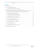
Dell Networking FC Flex IOM: Deployment of FCoE with Dell FC Flex IOM, Brocade FC switches, and Dell Compellent Storage Array Contents 1 Executive Summary .........................................................................................................................................5 2 Dell PowerEdge M1000e Overview ............................................................................................................ 6 2.1 Flex IO Expansion Modules (External Ports).......................
1 Executive Summary In the “Dell Networking FC Flex IOM: Infrastructure & Network Convergence w/ FCoE” whitepaper we demonstrated and explained the movement from a traditional non-converged LAN/SAN network to a converged LAN/SAN infrastructure and network and how the Dell MXL/IOA with Dell FC Flex IOM is an ideal solution for this transition.
2 Dell PowerEdge M1000e Overview The PowerEdge M1000e Modular Server Enclosure solution supports up to (32) server modules, and (6) network I/O modules. The M1000e contains a high performance and highly available passive midplane that connects server modules to the infrastructure components, power supplies, fans, integrated KVM and Chassis Management Controllers (CMC). The PowerEdge M1000e uses redundant and hot‐ pluggable components throughout to provide maximum uptime.
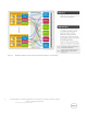
Figure 3 7 M1000e Midplane Dual/Quad Port Network Adaptor I/O Mappings Dell Networking FC Flex IOM: Deployment of FCoE with Dell FC Flex IOM, Brocade FC switches, and Dell Compellent Storage Array Deployment/Configuration Guide
2.1 Flex IO Expansion Modules (External Ports) The Dell I/O Modules will support a combination of Flex IO Modules. The four (4) different types of Flex IO expansion modules are: Figure 4 4-port 10Gbase-T FlexIO module (only one 10Gbase-T module can be used) 4-port 10Gb SFP+ FlexIO module 2-port 40Gb QSFP+ FlexIO module 4-port Fiber Channel 8Gb module FlexIO expansion modules NOTE: The 4 Port Fibre Channel 8Gb module can only be used with the release of 9.
3 Dell FC Flex IOM and Convergence on Dell MXL/IOA Overview The Dell FC Flex IO module provides the additional functionality to a Dell MXL/IOA blade switch to enable it to act as a NPIV Proxy Gateway (NPG) capable of bridging between Ethernet and FC. FC Flex IOM takes the convergence from the ToR down to the blade level consolidating infrastructure while still providing the benefits of network convergence and leveraging the backend FC SAN.
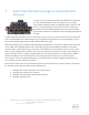
4 Converged Network Solution – Dell PowerEdge M1000e, Dell Compellent Storage Array, Brocade FC Switch, and Dell MXL/IOA w/ FC Flex IO as NPIV Proxy Gateway This solution demonstrates network and infrastructure convergence via Dell MXL blade switch w/ FC Flex IOM. The Dell PowerEdge M1000e chassis consists of one Dell PowerEdge M620 Blade Server with a 2-port Broadcom 57810 CNA and two Dell MXL blade switches each containing a FC Flex IO module.
Figure 5 Dell MXL w/ FC Flex IOM acting as a NPIV Proxy Gateway and allowing for a converged infrastructure This setup involves configuration on the CNA, server, MXL blade switches w/ FC Flex IOMs, LAN Dell S6000 switches, Brocade 6505 FC switches, and the Dell Compellent storage array. This document steps through the configuration one node at a time.
4.1 Broadcom 57810 CNA Configuration Broadcom offers the Broadcom BCM57810S in three formats for Dell servers: standard PCI Express, mezzanine card for Dell blade servers, and Network Daughter Card (NDC) for Dell blade servers. The Broadcom BCM57810S allows for NIC partitioning (NPAR) with up to four partitions per physical port and eight partitions total per 2-port adapter. A partition can be looked upon as a virtual port.
Figure 6 Broadcom 57810 CNA adapter view in Broadcom Advanced Control Suite 4 Note: In the current configuration (Figure 6), there are two ports and only one partition per port. This is because the adapter is in Single Function mode and NPAR is not being utilized. If NPAR is desired, configure it by clicking the Adapter BCM57810 label, clicking the + symbol to the right of Multi-function, clicking the Configure button and selecting NIC Partition from the drop down list (Figure 7).
Figure 7 14 Default ‘Single Function’ mode setting on Broadcom 57810 CNA Dell Networking FC Flex IOM: Deployment of FCoE with Dell FC Flex IOM, Brocade FC switches, and Dell Compellent Storage Array Deployment/Configuration Guide
3. Go to Control Panel > Network and Internet > Network and Sharing Center > Change adapter settings, The Broadcom Network Adapters are displayed. The two Broadcom 57810 CNA ports being utilized in this setup are highlighted (Figure 8).
4. Use the Broadcom Advanced Control Suite 4 to enable FCoE by selecting the single partition under each port and clicking the Configurations tab on the right. Click the + symbol next to Resource Reservations and click the Configure button. Check the checkbox next to FCoE (Figure 9). 5. Click Next and then Apply. Repeat this step to enable FCoE on the second port.
Figure 10 Windows Server 2008 R2 Enterprise detects Broadcom 57810 FCoE Adapter Figure 11 Broadcom 57810 CNA configured for FCoE Since the respective FCoE settings will be pushed down from the Dell MXL switch with FC Flex IOM via 17 Dell Networking FC Flex IOM: Deployment of FCoE with Dell FC Flex IOM, Brocade FC switches, and Dell Compellent Storage Array Deployment/Configuration Guide
Data Center Bridging Capability Exchange protocol (DCBX), the FCoE side requires no further configuration. 6. To configure the NIC for LAN traffic, select TEAM VIEW from the Filter drop down box (Figure 12).
7. Right click Teams and select Create Team. The Broadcom Teaming Wizard (Figure 13) will start.
8. Click Next, keep the default team name (Figure 14) and click Next again.
9. Click the radio button next to Smart Load Balancing™ and Failover (SLB) (Figure 15), and click next. Note: The switch will not be aware of the NIC team and no LAG configuration will be required on upstream switches.
10. Select one of the adapter ports to NIC team and click the Add button, repeat this for the second port. Both ports should now be listed under Team Members (Figure 16). Click Next.
11. The NIC team is completed as active-standby (Figure 17), so upon failover, the standby port will become active. Click Next.
12. Broadcom LiveLink is a feature that minimizes any downtime due to spanning tree loop determination when failing-over. In this setup, the ports connected to the server will be configured as edge ports and not participate in spanning tree so this option is left at the default of disabled (Figure 18). Click Next.
13. Select the Add VLAN option (Figure 19) and click Next.
14. Enter VLAN 5 for the VLAN Name (Figure 20) and click Next.
15. Select the Tagged radio button (Figure 21) and click Next.
16. Enter 5 for the VLAN tag value (Figure 22) and click Next.
17. Since there are no other VLANs to manage in this example, select No (Figure 23) and click Next.
18. Click Finish and then click Yes when prompted for confirmation (Figure 24).
19. The CNA configuration for both LAN and SAN traffic is now complete. The created NIC team can be displayed by expanding the adapters under TEAM VIEW (Figure 25).
20. Go to Control Panel > Network and Internet > Network and Sharing Center > Change adapter settings. The Network Connections are displayed. The two Broadcom 57810 CNA ports being utilized in this setup and the virtual adapter from the NIC teaming are highlighted in Figure 26. Figure 26 Viewing the NIC team and network connect in Windows Server 2008 R2 Enterprise The correct IP address information now needs to be assigned to the teamed adapter.
21. Right click Team1_VLAN5, click Properties. Select Internet Protocol Version 4 (TCP/IPv4) and click the Properties button. Enter the respective IP information (Figure 27), and click the OK button. Figure 27 Configuring the NIC team interface with the correct IP information The next step is to configure the Dell MXL switch w/ FC Flex IOM. 4.2 Dell MXL w/ FC Flex IOM Configuration Below is the full configuration for the Dell MXL w/ FC Flex IOM for both fabric A and fabric B.
2. Configure port to the CNA as a hybrid port. Create a LAN VLAN and tag it to both the tengigabitethernet 0/4 interface going to the respective CNA and port channel going up to VLT. 3. Enable FC capability 4. Create DCB Map and configure the priority-based flow control (PFC) and enhanced transmission selection (ETS) settings for LAN and SAN traffic. Priorities or Class of Service (CoS) are mapped to priority groups using the priority-pgid command.
Dell MXL Configuration (Fabric A) /* Enable RSTP (Enabled due to VLT config on S6000s) */ > enable > config terminal > protocol spanning-tree rstp > no disable > exit /* Configure Manangement Interface */ > interface management 0/0 > ip address 10.11.129.
Dell MXL Configuration (Fabric A) cont.
Dell MXL Configuration (Fabric B) /* Enable RSTP (Enabled due to VLT config on S6000s) */ > enable > config terminal > protocol spanning-tree rstp > no disable > exit /* Configure Manangement Interface */ > interface management 0/0 > ip address 10.11.129.
Dell MXL Configuration (Fabric B) cont.
4.3 Dell Compellent Storage Array Configuration The Dell Compellent Storage Center controllers are used to support various I/O adapters including FC, iSCSI, FCoE, and SAS. A Dell Compellent Storage Center consists of one or two controllers, FC switches, and one or more enclosures. In the current example, two Compellent SC8000 controllers, one Compellent SC220 enclosure, two FC switches, and one 4-port FC HBA card on each Compellent controller is used for the SAN network.
Figure 28 Storage Center System Manager GUI displays disk pool “Pool_1” with 1.64 TB free space 2. Since there are two fabrics, fabric A and fabric B, two fault domains are created. Domain 1 is already created by default and all the FC ports are currently in domain 1. To create another domain, click Storage Management on the top left of the webpage and then select System > Setup > Configure Local Ports. 3. Next, click the Edit Fault Domains button at the bottom right of the dialog box. 4.
5. Now, navigate back to the Configure Local Ports dialog and select the appropriate domain to put each port in. Each fabric should be in its own Domain; below all ports going to fabric A are put in Domain 1 and all ports going to fabric B are put in Domain 2. Figure 30 Assigning ports on Compellent Storage to respective Fault Domains Note: If you get a warning that paths are not balanced, navigate to the left-hand pane, right click Controllers and select Rebalance Local Ports.
Figure 31 Added Dell PowerEdge Server HBAs to ‘Server Object’ on Dell Compellent Storage Array The next step is to enable mulipathing on Windows Server 2008 R2 Enterprise. 7. Navigate to Start > Administrative Tools > Server Manager > Features > Add Features and select Multipath I/O. You can see in Figure 32 below that the Multipath I/O feature has been installed.
Figure 32 8. 43 Installing Windows Server 2008 R2 Enterprise Multipath I/O feature Navigate to Start > Control Panel > MPIO and click the Add button. When prompted for a Device Hardware ID, input COMPELNTCompellent Vol and click the OK button. The system will need to be restarted for the changes to take effect. Figure 33 displays the COMPELNTCompellent Vol text that you should see on the MPIO Devices tab in MPIO Properties once the system is brought back up.
Figure 33 Installing Windows Server 2008 R2 Enterprise Multipath I/O for Compellent array Next, create a volume and map it to a server object so the respective server can write to the FC storage array. 9. 44 Simply right click Volumes on the left-hand pane and select Çreate Volume to get started. During the process, you will be asked to select a Replay Profile; this is simply asking you how often snapshots/recovery points of the storage volume should be taken.
Figure 34 45 Created 20 GB “Finance_Data_Compellent” volume on Compellent array Dell Networking FC Flex IOM: Deployment of FCoE with Dell FC Flex IOM, Brocade FC switches, and Dell Compellent Storage Array Deployment/Configuration Guide
Figure 35 Confirming to keep the default value for ‘Replay Profiles’ 10. The last step in configuring the Dell Compellent Storage Center array is mapping the newly created volume to the server. Once you create the volume, you will be asked if you want to map it to a server object. You can do it at this time or later. If mapping the volume to a server object later, on the left-hand pane under Storage > Volumes, simply right click on the volume you just created and select Map Volume to Server.
Figure 36 Initialized and formatted virtual disk within Windows Server 2008 R2 Enterprise Note: The volume on the Compellent storage array displays in Windows just like a typical hard drive. Other than enabling FCoE on the CNA, no special configuration was needed.
Figure 37 Remote storage on Compellent as seen in Windows as drive ‘E:’ Compellent SC8000 Load Balancing Policy Options: The Compellent SC8000 controller uses Microsoft Multipath I/O (MPIO) for load balancing over ports. Microsoft MPIO is a framework that allows administrators to configure load balancing and failover processes for FC and iSCSI connected storage devices. You can configure load balancing to use up to 32 independent paths from the connected storage devices.
policies require Asymmetric Logical Unit Access (ALUA) support on the array and additional support through a DSM. Figure 38 Checking MPIO settings in Windows Server 2008 R2 Enterprise Additionally, there are two IO connection options available with the Dell Compellent Storage Center that allow multiple paths to be presented to the servers: Legacy Ports and Virtual Ports.
another port. Although a virtual disk can still only be written to from the controller that owns the disk, virtual ports allow for better performance in terms of failover as the virtual connection can simply be moved to another physical port in the same fault domain. To use virtual ports, all FC switches and HBAs must support N_Port ID Virtualization (NPIV).
1.
2.
To observe that the storage ports and FCoE ports are logged into the fabric, you can use the nsshow command on the Brocade FC switch. A small capture of the output of this command is shown below.
You can also see the node WWPN by looking at what is logged in on the physical port as shown in Figure 42 below.
Another useful FC switch command to check what ports are connected is switchshow.
4.5 1. To see information on NPIV devices logged into the fabric, use the show npiv devices command on the Dell MXL switch as shown below. Note the FCoE MAC is 0e:fc:02:01:0f:01 (the FCoE Map + FC_ID as expected). Figure 44 2. ‘show fip-snooping enode’ command output on fabric A Dell MXL switch To see all FCoE end-node (ENodes) , use the show fip-snooping enode command.
4. To see a list of configured fcoe-maps, use the show fcoe-map brief command. Figure 47 5. To see more detailed information on a given fcoe-map, use the show fcoe-map command. Notice below, the priority mapped to FCoE by default is 3.
5 Dell IOA w/ FC Flex IOM Configuration This example uses a similar topology as shown prior except instead of using the Dell MXLs in the Fabric A blade slot, the Dell IOAs with FC Flex IOMs in the Fabric B slot of the M1000e chassis are used. Another difference from the prior example in Section 4 is that instead of the Broadcom 57810 NDC CNA in the Fabric A slot of the server, the QLogic QME8262-k mezzanine CNA adapter inserted in the Fabric B slot of the server is used. 5.
Figure 49 Figure 50 59 QLogic QLE8262 CNA Configuration Dell Qlogic QLE8262 CNA QConvergeConsole screen Dell Networking FC Flex IOM: Deployment of FCoE with Dell FC Flex IOM, Brocade FC switches, and Dell Compellent Storage Array Deployment/Configuration Guide
Figure 51 Dell Qlogic QLE8262 CNA FcoE/NPAR Configuration Creating a NIC Team Since the NICs and HBAs are seen as virtual ports, you can treat them as separate entities and create a NIC team with the virtual CNA NIC ports. In Figures 51 - 54, you can see the two virtual NIC ports are NIC teamed using ‘Failsafe Team’. In this example, Windows Server 2008 R2 Enterprise is the operating system used. 2.
Figure 52 3. 61 ‘Team Management’ tab of port properties Now right click on the Teams folder and click Create Team. Choose the type of NIC teaming you desire. In this example we will demonstrate with Failsafe Team. Next, select the ports to add to the NIC team and select the primary adapter. The rest of the settings we leave as default. Figure 53 displays the virtual port NIC team with two virtual NIC ports as members.
Figure 53 62 NIC teaming virtual NIC ports with Failsafe Team Dell Networking FC Flex IOM: Deployment of FCoE with Dell FC Flex IOM, Brocade FC switches, and Dell Compellent Storage Array Deployment/Configuration Guide
Figure 54 Dell QLogic QLE8262 adapter propertise displaying the created NIC team As far as the network configuration for the LAN, since Failsafe Team is utilized, there is no special configuration that needs to be done on the IOA switches. You can simply have one link going to each IOA switch with one port in active mode and the other in standby mode. 4. 63 In this example, the LAN traffic is on VLAN 5.
Figure 55 Tagging the NIC team with VLAN 5 The NIC team will now show in Windows as a new virtual adapter as shown in Figure 56 and Figure 57.
Figure 57 NIC team virtual adapter as seen in ‘Device Manager’ in Windows 5.2 Dell IOA w/ FC Flex IOM Configuration 5.2.1 Default Configuration If only layer 2 functionality is required, FC Flex IOM can be used with the Dell IOA blade switch to provide Ethernet-FC bridging capability instead of the Dell MXL blade switch which also provides advanced layer 3 functionality. In addition, in the default standalone mode, the Dell IOA blade switch requires zero-touch configuration.
Figure 58 Dell IOA w/ FC Flex IOM acting as a NPIV Proxy Gateway and allowing for a converged infrastructure By simply inserting the Dell IOA blade switch w/ FC Flex IOM into the Dell M1000e chassis, you can see below that the end-node is able to log into the SAN A fabric without any configuration needed. In default standalone mode, the Dell PowerEdge M I/O Aggregator requires zero-touch configuration in terms of setting up the environment for FCoE.
preconfiguration already applied by default, once the server is configured properly, the IOA will automatically function as a FCoE NPIV Proxy Gateway. For the Dell, MXL setup in figure 5 prior in this document, we manually applied much of the same configuration such as uplink-failure detection. By simply inserting the Dell IOA blade switch w/ FC Flex IOM into the Dell M1000e chassis, you can see below that the end-node is able to log into the SAN A fabric without any configuration needed.
Figure 62 Server connecting port configuration on fabric A IOA switch Figure 63 Port-channel member interface configuration on fabric A IOA switch Figure 64 Port-channel interface configuration on fabric A IOA switch Dell Networking FC Flex IOM: Deployment of FCoE with Dell FC Flex IOM, Brocade FC switches, and Dell Compellent Storage Array Deployment/Configuration Guide
Figure 65 69 FC interface configuration Dell Networking FC Flex IOM: Deployment of FCoE with Dell FC Flex IOM, Brocade FC switches, and Dell Compellent Storage Array Deployment/Configuration Guide
5.2.2 Programmable-mux mode It’s also possible to deploy Dell IOA w/ FC Flex IOM using Programmable-mux mode. This allows for cli configuration of the IOA similar to the MXL. This mode can be useful if you want to customize the configuration based on specific requirements such as multiple upstream LAGs or multiple FC fabrics. To set the IOA to programmable-mux mode use the stack-unit iom-mode programmable-mux command from config mode as shown further below in Figure 66.
Figure 67 'show npiv devices' command output on fabric A IOA switch To see currently active FCoE VN_Port sessions, use the show fip-snooping sessions command. Figure 68 'show fip-snooping sessions' command output on fabric A IOA switch To see all FCoE end-node (ENodes) , use the show fip-snooping enode command. Figure 69 'show fip-snooping enode' command output on fabric A IOA switch To see a list of configured fcoe-maps, use the show fcoe-map brief command.
To see more detailed information on a given fcoe-map, use the show fcoe-map command. Notice below, the priority mapped to FCoE by default is 3.
6 M1000e FlexAddress enablement When working with network adaptors that provide a MAC address as well as a World Wide Port and Node name, it’s important to understand where these addresses originate. The M1000e chassis has a feature called Flexaddressing which allows for a virtual MAC address/WWPN to be linked to a server, therefore, if the CNA/adapter is changed later, zoning or configuration on upstream switches does not need to be modified.
Note: When the FlexAddress feature is deployed for the first time on a given server, it requires at least one powerdown and power-up sequence of the server for the FlexAddress feature to take effect. Certain network configurations may require refreshing of network tables, such as ARP tables on IP switches and routers in order for new MAC/WWNs to be logged in. To check that FlexAddressing is enabled: Figure 73 FlexAddress Enablement Confirmation 1. Click on Server Overview 2. Click on Properties 3.