
Users Guide


Table Of Contents
- Dell 10Gb Ethernet Pass Through -k for M1000e User Manual
- Related Documentation
- Revision History
- About this Manual
- 1 Overview
- 2 Installation and Basic Operation
- 2.1 Unpacking the Pass Through Module
- 2.2 Insertion and Removal of the PTM
- 2.2.1 PTM Insertion
- 2.2.2 PTM Removal
- 2.3 Connecting the External Ports
- 2.3.1 10 Gigabit Ethernet SFP+ Modules
- 2.3.2 Installation and Removal of Optical Transceiver Modules
- 2.4 LED Indicators
- 2.4.1 System LEDs
- 2.4.2 Port LEDs
- 2.4.3 Installation Safety Warnings
- 2.4.4 Mechanical Installation
- 2.4.5 Cable Installation
- 3 Troubleshooting
- Appendix A: Specifications
- Appendix B: Supported Cables and Media Types
- Appendix C: EMC Certification Statements
- Appendix D: Interface Connector Pinouts
Dell -10GbE PTM Rev 1.0
23
Appendix D: Interface Connector Pinouts
D.1: SFP+ Interface
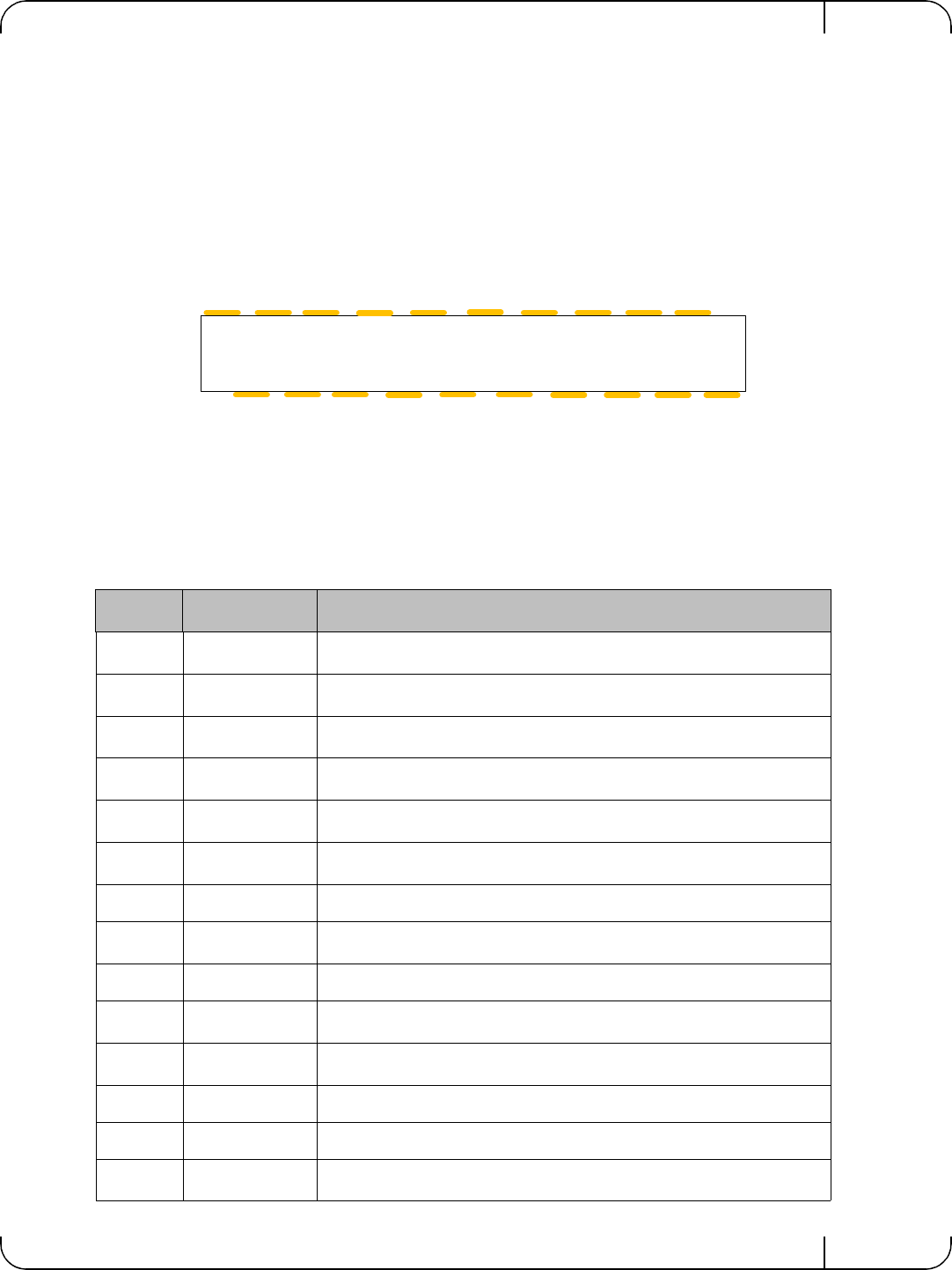
Figure 8: SFP+ Connector Pinout - Rear View of Module With Pin Placement
Table 9 - SFP+ Pinout
Pin Symbol Name Description
1 VeeT
Transmitter Ground (Common with Receiver Ground)
a
2 TX_Fault
Transmitter Fault.
b
3 TX_Disable
Transmitter Disable. Laser output disabled on high or open.
c
4 SDA
2-wire Serial Interface Data Line
d
5 SCL
2-wire Serial Interface Clock Line
d
6 MOD_ABS
Module Absent. Grounded within the module
d
7 RS0 No connection required
8 RX_LOS
Loss of Signal indication. Logic 0 indicates normal operation.
e
9 RS1 No connection required
10 VeeR
Receiver Ground (Common with Transmitter Ground)
a
11 VeeR
Receiver Ground (Common with Transmitter Ground)
a
12 RD- Receiver Inverted DATA out. AC Coupled
13 RD+ Receiver Non-inverted DATA out. AC Coupled
14 VeeR
Receiver Ground (Common with Transmitter Ground)
a
VeeT
VeeT
VeeT
TX_Fault
TX_Disable
SDA
SCL
MOD_ABS
RS0
RX_LOS
RS1
VeeR
VeeR
VeeR
VccT
VccR
TD+
TD-
RD-
RD+
1
2
3
4
5
6
7
8
9
1
2
3
4
5
6
7
8
9
0
1
1
1
1
1
1
1
1
1
2
10