
Users Guide


Table Of Contents
- Dell 10Gb Ethernet Pass Through -k for M1000e User Manual
- Related Documentation
- Revision History
- About this Manual
- 1 Overview
- 2 Installation and Basic Operation
- 2.1 Unpacking the Pass Through Module
- 2.2 Insertion and Removal of the PTM
- 2.2.1 PTM Insertion
- 2.2.2 PTM Removal
- 2.3 Connecting the External Ports
- 2.3.1 10 Gigabit Ethernet SFP+ Modules
- 2.3.2 Installation and Removal of Optical Transceiver Modules
- 2.4 LED Indicators
- 2.4.1 System LEDs
- 2.4.2 Port LEDs
- 2.4.3 Installation Safety Warnings
- 2.4.4 Mechanical Installation
- 2.4.5 Cable Installation
- 3 Troubleshooting
- Appendix A: Specifications
- Appendix B: Supported Cables and Media Types
- Appendix C: EMC Certification Statements
- Appendix D: Interface Connector Pinouts
OverviewRev 1.0
6
1Overview
The PTM is an I/O module designed for the PowerEdge M1000e Dell Chassis. The product pro-
vides 10Gigabit connectivity for blade servers to Ethernet LANs. The product supports the follow-
ing Ethernet protocols.
Each front panel port provides connectivity to the blade with the corresponding number in the
chassis.
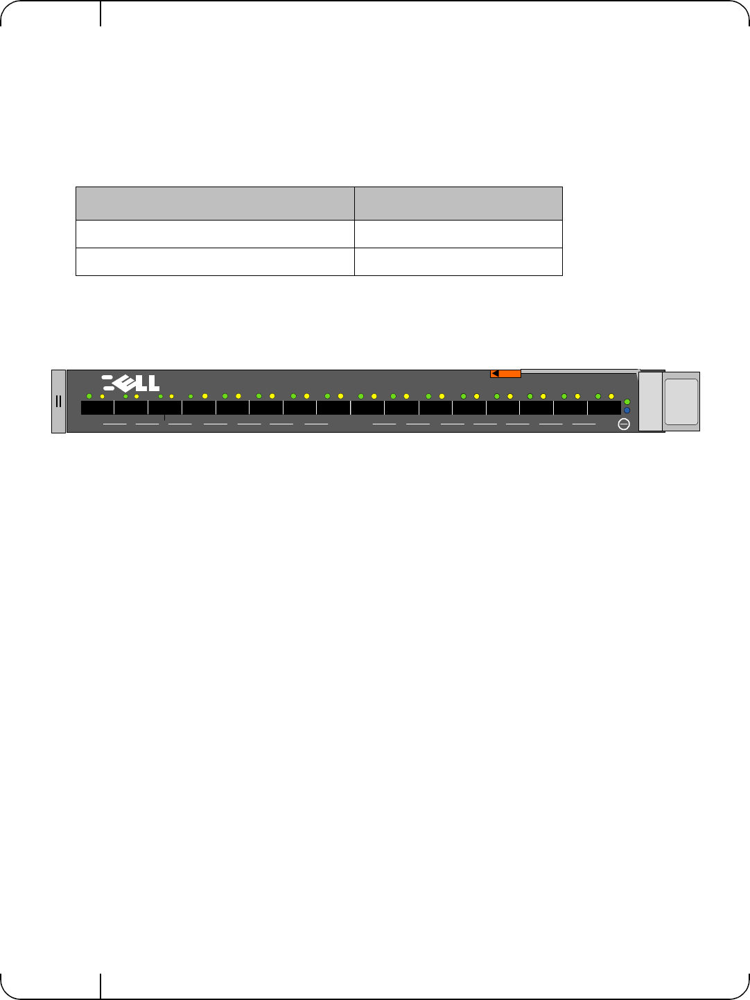
Figure 1: Dell 10Gb Ethernet Pass Through -k module Front Panel
1.1 Features
The PTM feature set includes:
Internal Links
• 16 ports of 10Gb Ethernet 10GBASE-KR through the backplane
External links
• 16 SFP+ front panel ports of 10Gb Ethernet
IEEE and Other Ethernet Standards Compliance
• IEEE 802.3ae 10Gigabit Ethernet support
• IEEE 802.3ap Ethernet Operation over Electrical Backplanes
• Including KR startup protocol and Forward Error Correction (FEC) support
• Supports KR auto-negotiation
• Jumbo Frames up to 9K support
Connectors and Cabling
• Twin Axial Pair connector
• Optical modules for SR and LR
• All ports support active cables
Table 3 - Protocols
Physical Connections Pass Through -k Protocol
Blade Servers to PTM (Internal Links) KR
Front Panel Ports (External Links) 10G XFI
9
10
11
12
13
14
15
16
1
2
3
4
5
6
7
8
D
D
D
10 Gb Ethernet Pass Through -k