
Users Guide


Table Of Contents
- Dell 10Gb Ethernet Pass Through -k for M1000e User Manual
- Related Documentation
- Revision History
- About this Manual
- 1 Overview
- 2 Installation and Basic Operation
- 2.1 Unpacking the Pass Through Module
- 2.2 Insertion and Removal of the PTM
- 2.2.1 PTM Insertion
- 2.2.2 PTM Removal
- 2.3 Connecting the External Ports
- 2.3.1 10 Gigabit Ethernet SFP+ Modules
- 2.3.2 Installation and Removal of Optical Transceiver Modules
- 2.4 LED Indicators
- 2.4.1 System LEDs
- 2.4.2 Port LEDs
- 2.4.3 Installation Safety Warnings
- 2.4.4 Mechanical Installation
- 2.4.5 Cable Installation
- 3 Troubleshooting
- Appendix A: Specifications
- Appendix B: Supported Cables and Media Types
- Appendix C: EMC Certification Statements
- Appendix D: Interface Connector Pinouts
Installation and Basic OperationRev 1.0
8
2 Installation and Basic Operation
2.1 Unpacking the Pass Through Module
Before you install your new PTM, unpack it and make sure that there is no visible damage that
may have occurred during shipping. Your package should contain the following items:
• Dell 10Gb Ethernet Pass Through -k module for Blade Servers
• This Users Manual
The PTM is shipped without optical modules.
If anything in the package is damaged or missing, please contact your customer representative
immediately.
2.2 Insertion and Removal of the PTM
The Dell 10Gb Ethernet Pass Through -k module may be plugged into fabric slots A1, A2, B1, B2,
C1, and C2.
Determine which slot to use, based on desired system configuration.
2.2.1 PTM Insertion
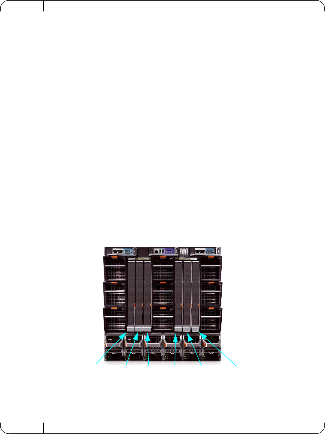
Insert the PTM into the chassis as shown in the following diagram:
Figure 3: Dell Chassis Slots for the PTM
Slot A1
Slot B1 Slot C1
Slot A2
Slot B2Slot C2