
Configuration manual


40-6
Cisco Catalyst Blade Switch 3130 and 3032 for Dell Software Configuration Guide
OL-13270-03
Chapter 40 Configuring HSRP
Configuring HSRP
• Configuring HSRP Authentication and Timers, page 40-11
• Enabling HSRP Support for ICMP Redirect Messages, page 40-12
Default HSRP Configuration
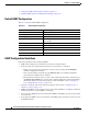
Table 40-1 shows the default HSRP configuration.
HSRP Configuration Guidelines
Follow these guidelines when configuring HSRP:
• HSRP can be configured on a maximum of 32 VLAN or routing interfaces.
• In the procedures, the specified interface must be one of these Layer 3 interfaces:
–
Routed port: a physical port configured as a Layer 3 port by entering the no switchport
interface configuration command.
–
SVI: a VLAN interface created by using the interface vlan vlan_id global configuration
command and by default a Layer
3 interface.
–
Etherchannel port channel in Layer 3 mode: a port-channel logical interface created by using
the interface port-channel port-channel-number global configuration command and binding
the Ethernet interface into the channel group. For more information, see the
“Configuring
Layer 3 EtherChannels” section on page 37-14.
• All Layer 3 interfaces must have IP addresses assigned to them. See the “Configuring Layer 3
Interfaces” section on page 11-24.
• HSRPv2 and HSRPv1 can be configured on the same switch if HSRPv2 is configured on different
interfaces than those on which HSRPv1 is configured.
• The version of an HSRP group can be changed from HSRPv2 to HSRPv1 only if the group number
is less than 256.
• If you change the HSRP version on an interface, each HSRP group resets because it now has a new
virtual MAC address.
Ta b l e 40-1 Default HSRP Configuration
Feature Default Setting
HSRP version Version 1
HSRP groups None configured
Standby group number 0
Standby MAC address System assigned as: 0000.0c07.acXX, where XX is the HSRP
group number
Standby priority 100
Standby delay 0 (no delay)
Standby track interface priority 10
Standby hello time 3 seconds
Standby holdtime 10 seconds