Dell PowerEdge M420 Systems Owner's Manual Regulatory Model: QHB Regulatory Type: QHB Series
Notes, Cautions, and Warnings NOTE: A NOTE indicates important information that helps you make better use of your computer. CAUTION: A CAUTION indicates either potential damage to hardware or loss of data and tells you how to avoid the problem. WARNING: A WARNING indicates a potential for property damage, personal injury, or death. Information in this publication is subject to change without notice. © 2012 Dell Inc. All rights reserved.
Contents Notes, Cautions, and Warnings...................................................................................................2 1 About Your System......................................................................................................................7 Overview...................................................................................................................................................................7 Front-Panel Features And Indicators..........................
3 Installing Blade Components..................................................................................................25 Recommended Tools..............................................................................................................................................25 Removing And Installing A Sleeve..........................................................................................................................25 Removing The Sleeve............................................
Removing Memory Modules............................................................................................................................47 Installing Memory Modules.............................................................................................................................48 Management Riser Card.........................................................................................................................................49 Removing The Management Riser Card..............
Contacting Dell.....................................................................................................................................................
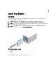
About Your System 1 Overview Your system includes up to four quarter-height blades installed in a sleeve. To function as a system, the sleeve is inserted into an M1000e enclosure (chassis). CAUTION: Exercise care while handling the sleeve to prevent damage to the internal components. NOTE: To ensure proper operation and cooling, all blade slots in the sleeve must be populated at all times with either a blade or quarter-height blade blank(s).
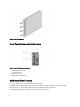
Figure 2. Blade Slot Numbering Front-Panel Features And Indicators Figure 3. Front-Panel Features and Indicators 1. 2. 3. 4. blade handle release button solid state drives (2) USB connectors (2) blade power button/indicator Solid State Drive Features Your system supports two 1.8 inch uSATA Solid State Drives (SSD). The SSDs plug into the SSD backplane inside the blade.
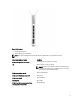
Figure 4. SSD Features 1. activity indicator (green) 2. status indicator (green and amber) NOTE: If the SSD is in Advanced Host Controller Interface (AHCI) mode, the status LED remains off. Drive-Status Indicator Pattern Condition Blinks green two times per second Identifying drive or preparing for removal Off Drive ready for insertion or removal NOTE: The drive status indicator remains off until all SSDs are initialized after system power is applied.
Other Information You May Need WARNING: See the safety and regulatory information that shipped with your system. Warranty information may be included within this document or as a separate document. • The Getting Started Guide provides an overview of system features, setting up your system, and technical specifications. • The Rack Installation Instructions included with your rack solution describes how to install your system into a rack.
Using The System Setup And Boot Manager 2 System Setup enables you to manage your system hardware and specify BIOS-level options. The following keystrokes provide access to system features during startup: Keystroke Description Enters the System Setup. Enters System Services, which opens the Dell Lifecycle Controller 2 (LC2). The Dell LC2 allows you to access utilities such as embedded system diagnostics. For more information, see the Dell LC2 documentation.
NOTE: Operating systems must be UEFI-compatible to be installed from the UEFI boot mode. DOS and 32-bit operating systems do not support UEFI and can only be installed from the BIOS boot mode. NOTE: For the latest information on supported operating systems, see dell.com/ossupport. Entering System Setup 1. Turn on or restart your system. 2.
Menu Item Description iDRAC Settings This option is used to view and configure iDRAC settings. Device Settings This option is used to view and configure device settings. System BIOS Screen NOTE: The options for System Setup change based on the system configuration. NOTE: System Setup defaults are listed under their respective options in the following sections, where applicable. Menu Item Description iDRAC Settings This option is used to view and configure iDRAC settings.
Memory Settings Screen Menu Item Description System Memory Size Displays the amount of memory installed in the system. System Memory Type Displays the type of memory installed in the system. System Memory Speed Displays the system memory speed. System Memory Voltage Displays the system memory voltage. Video Memory Displays the amount of video memory. System Memory Testing Specifies whether system memory tests are run during system boot. Options are Enabled and Disabled.
Menu Item Description DCU Streamer Prefetcher Allows you to enable or disable DCU streamer prefetcher. By default, the DCU Streamer Prefetcher option is set to Enabled. DCU IP Prefetcher Allows you to enable or disable DCU IP prefetcher. By default, the DCU IP Prefetcher option is set to Enabled. Execute Disable Allows you enable or disable execute disable memory protection technology. By default, the Execute Disable option is set to Enabled.
Integrated Devices Screen Menu Item Description Integrated RAID Controller Allows you to enable or disable the integrated RAID controller. By default, the Integrated RAID Controller option is set to Enabled. User Accessible USB Ports Allows you to set the user accessible ports. Selecting All Ports Off disables all USB ports. By default, the User Accessible USB Ports option is set to All Ports On. Internal SD Card Redundancy If set to Mirror mode, data is written on both SD cards.
Menu Item Description Remote Terminal Type Allows you to set the remote console terminal type. By default, the Remote Terminal Type option is set to VT 100/VT220. Redirection After Boot Allows you to enable or disable to the BIOS console redirection when the operating system is loaded. By default, the Redirection After Boot option is set to Enabled. System Profile Settings Screen Menu Item Description System Profile Allows you to set the system profile.
System Security Screen Menu Item Description Intel AES-NI The Intel AES-In option improves the speed of applications by performing encryption and decryption using the Advanced Encryption Standard set and is set to Enabled by default. System Password Allows you to set the system password. This option is read-only if the password jumper is not installed in the system. Setup Password Allows you to set the setup password. This option is read-only if the password jumper is not installed in the system.
Menu Item Description Report Keyboard Errors Allows you to set whether keyboard-related error messages are reported during system boot. By default, the Report Keyboard Errors field is set to Report. F1/F2 Prompt on Error Allows you to enable or disable the F1/F2 prompt on error. By default, F1/F2 Prompt on Error is set to Enabled. In-System Characterization This field enables or disables In-System Characterization. By default, In-System Characterization is set to Enabled.
– The following special characters are allowed: space, (”), (+), (,), (-), (.), (/), (;), ([), (\), (]), (`). A message prompts you to re-enter the system password. 6. Re-enter the system password that you entered earlier and click OK. 7. Select Setup Password, enter your system password and press or . A message prompts you to re-enter the setup password. 8. Re-enter the setup password that you entered earlier and click OK. 9. Press to save the changes.
NOTE: You can disable password security while logging on to the system. To disable the password security, turn on or reboot your system, type your password and press . Operating With A Setup Password Enabled If Setup Password is Enabled, enter the correct setup password before modifying most of the System Setup options.
Key Description Moves to the previous page till you view the main screen. Pressing in the main screen exits System Setup. A message prompts you to save any unsaved changes. Displays the System Setup help file. NOTE: For most of the options, any changes that you make are recorded but do not take effect until you restart the system. Boot Manager Screen Menu Item Description Continue Normal Boot The system attempts to boot to devices starting with the first item in the boot order.
iDRAC Settings Utility The iDRAC Settings utility is an interface to setup and configure the iDRAC parameters using UEFI. You can enable or disable various iDRAC parameters using the iDRAC7 Settings Utility, for example: NOTE: Some of the features mentioned in the list may require the iDRAC7 Enterprise License upgrade.
Installing Blade Components 3 Recommended Tools You may need the following items to perform the procedures in this section: • #1 and #2 Phillips screwdrivers • T10 and T15 Torx screwdrivers • Wrist grounding strap (connected to ground) Removing And Installing A Sleeve CAUTION: Many repairs may only be done by a certified service technician.
Figure 5. Removing and Installing a Sleeve 1. 2. 3. 4. sleeve handle cover sleeve handle sleeve/blade slot guide rail on sleeve 5. guide rail on enclosure 6. sleeve Installing The Sleeve 1. Remove the I/O connector covers from the I/O connectors on the sleeve and save for future use. 2. Remove the cover from the sleeve handle. NOTE: To ensure optimal thermal performance, do not replace the cover on the sleeve handle after the sleeve is installed in the enclosure. 3.
Removing And Installing A Blade CAUTION: Many repairs may only be done by a certified service technician. You should only perform troubleshooting and simple repairs as authorized in your product documentation, or as directed by the online or telephone service and support team. Damage due to servicing that is not authorized by Dell is not covered by your warranty. Read and follow the safety instructions that came with the product. Removing A Blade 1.
Inside The Blade Figure 7. Inside the Blade 1. 2. 3. 4. 5. 6. 7. 8. blade system board release handle mezzanine card blank processor/DIMM blank LOM riser card connector heat sink (for processor 1) memory modules (3) (for processor 2) SSD backplane solid state drives (2) 9. 10. 11. 12. 13. 14.
Removing A Mezzanine Card CAUTION: Many repairs may only be done by a certified service technician. You should only perform troubleshooting and simple repairs as authorized in your product documentation, or as directed by the online or telephone service and support team. Damage due to servicing that is not authorized by Dell is not covered by your warranty. Read and follow the safety instructions that came with the product. 1. Remove the blade from the sleeve. 2.
Figure 9. Removing and Installing a Mezzanine Blank 1. 2. 3. 4. 5. tabs under the mezzanine blank (4) mezzanine blank locking tab on the side of the mezzanine blank mezzanine card slot mezzanine card retention latch Installing A Mezzanine Card CAUTION: Many repairs may only be done by a certified service technician. You should only perform troubleshooting and simple repairs as authorized in your product documentation, or as directed by the online or telephone service and support team.
LOM Riser Card Removing The LOM Riser Card CAUTION: Many repairs may only be done by a certified service technician. You should only perform troubleshooting and simple repairs as authorized in your product documentation, or as directed by the online or telephone service and support team. Damage due to servicing that is not authorized by Dell is not covered by your warranty. Read and follow the safety instructions that came with the product. 1. Remove the blade from the sleeve. 2.
3. Install the blade in the sleeve. Solid State Drives • The system supports up to two 1.8 inch uSATA Solid State Drives (SSDs). • All SSDs connect to the blade system board through the SSD backplane. • SSDs are supplied in special hot-swappable drive carriers that fit in the SSD slots. • For a single SSD configuration, an SSD blank must be installed in the other drive bay to maintain proper cooling airflow.
Installing A Solid State Drive CAUTION: When a replacement hot-swappable SSD is installed and the blade is powered on, the SSD automatically begins to rebuild. Make absolutely sure that the replacement SSD is blank or contains data that you wish to have over-written. Any data on the replacement SSD is immediately lost after the SSD is installed. NOTE: Not all operating systems support hot-swappable drive installation. See the documentation supplied with your operating system. 1.
Figure 12. Removing and Installing an SSD Into an SSD Carrier 1. 2. 3. 4. 5. arrows (2) SSD carrier SSD SSD connectors connector alignment label Installing An SSD In The SSD Carrier 1. Align the SSD with the SSD carrier so that the connectors on the SSD face up and match the connector alignment label on the SSD carrier. CAUTION: To avoid damaging the SSD or the SSD carrier, do not use excessive force. 2. Slide the SSD into the SSD carrier until it is secured inside the SSD carrier.
3. Slide the blue release latches up. 4. Slide the SSD backplane away from the card-edge connector on the management riser card and lift the SSD backplane out of the blade. Figure 13. Removing and Installing the SSD Backplane 1. 2. 3. 4. SSD backplane SSD backplane connector card-edge connector (on management riser card) release latches (2) Installing The SSD Backplane 1. Align the backplane connector with the card edge connector on the management riser card. 2.
Processors • Your system supports up to two Intel Xeon processor E5-2400 product family. • Single-processor configuration is supported. Use the following procedure when: • Installing an additional processor • Replacing a processor Removing A Processor CAUTION: Many repairs may only be done by a certified service technician. You should only perform troubleshooting and simple repairs as authorized in your product documentation, or as directed by the online or telephone service and support team.
Figure 14. Removing and Installing a Heat Sink 1. heat sink 2. retention sockets (2) 3. retention screws (2) 4. Use a clean, lint-free cloth to remove any thermal grease from the surface of the processor shield. CAUTION: The processor is held in its socket under strong pressure. Be aware that the release lever can spring up suddenly if not firmly grasped. 5. Position your thumb firmly over the processor socket-release lever and release the lever from the locked position.
NOTE: For more information on installing a processor/DIMM blank, see Removing A Processor/DIMM Blank. Figure 15. Removing and Installing a Processor 1. 2. 3. 4. processor processor shield notches in the processor (4) socket keys (4) 5. pin-1 indicator (on the processor socket) 6. pin-1 indicator (on the processor) 7. socket-release lever Installing A Processor CAUTION: Many repairs may only be done by a certified service technician.
CAUTION: Positioning the processor incorrectly can permanently damage the system board or the processor. Be careful not to bend the pins in the socket. CAUTION: Do not use force to seat the processor. When the processor is positioned correctly, it engages easily into the socket. 5. Install the processor in the socket: a) Identify the pin-1 corner of the processor by locating the tiny gold triangle on one corner of the processor.
1. Remove the blade from the sleeve. 2. To disengage the battery from the battery connector, support the battery connector by pressing on the sides of the connector, and push the battery to the positive side of the connector. 3. Lift the battery out of the securing tabs of the battery connector. 4. To install a new system battery: a) Support the battery connector by pressing down firmly on the sides of the connector.
WARNING: The memory modules are hot to the touch for some time after the system has been powered down. Allow time for the memory modules to cool before handling them. Handle the memory modules by the card edges and avoid touching the components. 2. Remove the SD card and the vFlash card. 3. Remove the mezzanine card/blank. 4. Remove the SSDs. NOTE: If you are removing both SSDs, label them so you can replace them in their original locations. 5. Remove the SSD backplane.
c) LOM riser card 2. Slide the new blade system board into the open end of the blade chassis until the blade release latch engages. NOTE: Ensure that the system board is parallel with the chassis. 3. Replace the mezzanine card. 4. Reinstall the SSD backplane. 5. Replace the SSD(s). If there are two drives, be sure to reinstall them in their original locations. 6. Install the SD card(s). 7. Install the blade in the sleeve. 8. Import your new or existing iDRAC Enterprise license.
Figure 18. Removing and Installing a Processor/DIMM Blank 1. 2. 3. 4. processor socket processor/DIMM blank tabs (2) heat sink retention sockets (2) Installing A Processor/DIMM Blank 1. Remove the blade from the sleeve. 2. If installed, remove the processor and heat sink. For more information, see Removing A Processor. 3. Remove the blade system board. For more information, see Removing The Blade System Board. 4.
Memory bus operating frequency can be 1600 MT/s or 1333 MT/s depending on: • DIMM configuration (number of ranks) • maximum frequency of the DIMMs • DIMM operating voltage • system profile selected (for example, Performance Optimized, Custom, or Dense Configuration Optimized) • maximum supported DIMM frequency of the processors The following table shows the memory populations and operating frequencies for the supported configurations.
General Memory Module Installation Guidelines This system supports Flexible Memory Configuration, enabling the system to be configured and run in any valid chipset architectural configuration. The following are the recommended guidelines for best performance: • x4 and x8 DRAM based DIMMs can be mixed. For more information, see Mode-Specific Guidelines. • Populate DIMM sockets only if a processor is installed. For single-processor systems, sockets A1 to A3 are available.
NOTE: Memory sparing does not offer protection against a multi-bit uncorrectable error. NOTE: Both Advanced ECC/Lockstep and Optimizer modes support Memory Sparing. Memory Mirroring Memory Mirroring offers the strongest DIMM reliability mode compared to all other modes, providing improved uncorrectable multi-bit failure protection. In a mirrored configuration, the total available system memory is one half of the total installed physical memory.
System Capacity (in GB) DIMM Size (in GB) Number of DIMMs Organization and Speed DIMM Slot Population 12 2 6 1R x8, 1333 MT/s A1, A2, A3, B1, B2, B3 24 4 6 1R x4, 1333 MT/s 2R x8, 1333 MT/s 2R x8, 1600 MT/s A1, A2, A3, B1, B2, B3 48 8 6 2R x4, 1333 MT/s 2R x4, 1600 MT/s A1, A2, A3, B1, B2, B3 96 16 6 2R x4, 1333 MT/s 2R x4, 1600 MT/s A1, A2, A3, B1, B2, B3 192 32 6 4R x4, 1333 MT/s A1, A2, A3, B1, B2, B3 Removing Memory Modules WARNING: The DIMMs are hot to touch for some time
Figure 20. Removing and Installing a Memory Module or Memory Module Blank 1. 2. 3. 4. 5. memory module or memory module blank edge connector ejectors (2) socket alignment key Installing Memory Modules WARNING: The memory modules are hot to the touch for some time after the system has been powered down. Allow time for the memory modules to cool before handling them. Handle the memory modules by the card edges and avoid touching the components on the memory module.
5. Align the memory module's edge connector with the alignment key on the memory module socket, and insert the memory module in the socket. NOTE: The memory module socket has an alignment key that allows you to install the memory module in the socket in only one way. 6. Press down on the memory module with your thumbs to lock the memory module into the socket.
Figure 21. Removing and Installing the Management Riser Card 1. 2. 3. 4. management riser card screws (3) system configuration jumpers management riser card connector Installing The Management Riser Card CAUTION: Many repairs may only be done by a certified service technician. You should only perform troubleshooting and simple repairs as authorized in your product documentation, or as directed by the online or telephone service and support team.
NOTE: If the Redundancy option is set to Mirror mode in the Integrated Devices screen of the system setup, you must follow the instructions in step 5 through step 7 to avoid loss of data. 2. Remove the blade from the sleeve. 3. If the redundancy option is set to Disabled, replace the failed SD card with a new SD card. 4. Replace the SD card with a new SD card. 5. Install the blade in the sleeve. 6. Enter the System Setup and ensure that the Internal SD Card Port and Redundancy mode is enabled. 7.
Figure 23. Replacing the SD vFlash Card 1. SD vFlash card 2.
Troubleshooting Your System 4 Safety First—For You and Your System CAUTION: Many repairs may only be done by a certified service technician. You should only perform troubleshooting and simple repairs as authorized in your product documentation, or as directed by the online or telephone service and support team. Damage due to servicing that is not authorized by Dell is not covered by your warranty. Read and follow the safety instructions that came with the product.
Troubleshooting Solid State Drives CAUTION: Many repairs may only be done by a certified service technician. You should only perform troubleshooting and simple repairs as authorized in your product documentation, or as directed by the online or telephone service and support team. Damage due to servicing that is not authorized by Dell is not covered by your warranty. Read and follow the safety instructions that came with the product. CAUTION: This troubleshooting procedure can destroy data stored on the SSD.
NOTE: SD card slot 2 referred in this procedure is the vFlash SD card slot. You can install an SD card in SD card slot 2 to enable the Internal SD Card Redundancy option in the Integrated Devices screen of the System Setup. 1. Enter the System Setup and ensure that the Internal SD Card Port is enabled. 2. Note the Internal SD Card Redundancy option enabled in the Integrated Devices screen of the System Setup (Mirror or Disabled).
Troubleshooting The NVRAM Backup Battery CAUTION: Many repairs may only be done by a certified service technician. You should only perform troubleshooting and simple repairs as authorized in your product documentation, or as directed by the online or telephone service and support team. Damage due to servicing that is not authorized by Dell is not covered by your warranty. Read and follow the safety instructions that came with the product.
Using System Diagnostics 5 If you experience a problem with your system, run the system diagnostics before contacting Dell for technical assistance. The purpose of running system diagnostics is to test your system hardware without requiring additional equipment or risking data loss. If you are unable to fix the problem yourself, service and support personnel can use the diagnostics results to help you solve the problem.
The ePSA Pre-boot System Assessment window is displayed, listing all devices detected in the system. The diagnostics starts executing the tests on all the detected devices. System Diagnostic Controls Menu Description Configuration Displays the configuration and status information of all detected devices. Results Displays the results of all tests that are executed. System Health Provides the current overview of the system performance.
Jumpers And Connectors 6 System Board Jumper Settings CAUTION: Many repairs may only be done by a certified service technician. You should only perform troubleshooting and simple repairs as authorized in your product documentation, or as directed by the online or telephone service and support team. Damage due to servicing that is not authorized by Dell is not covered by your warranty. Read and follow the safety instructions that came with the product.
Item Connector Description 3 MEZZ Mezzanine card connector 4 - Blade connector to the sleeve interposer card 5 J_LOM_RISER LOM riser card connector 6 CPU1 Processor socket 1 7 BAT1 Connector for the 3.0 V coin cell battery 8 B1, B2, B3 Memory module sockets (for processor 2) 9 J_PERC Management riser card connector 10 USB2 USB connector 11 USB1 USB connector Disabling A Forgotten Password The blade's software security features include a system password and a setup password.
Technical Specifications 7 Processor Processor type One or two Intel Xeon processor E5-2400 product family Memory Architecture 1600 MT/s or 1333 MT/s, DDR3 and LV-DDR3 DIMMs Memory module sockets Six 240-pin Memory module capacities RDIMMs 2 GB (single-rank), 4 GB (single- and dual-rank), 8 GB (dualrank), 16 GB (dual-rank), and 32 GB (quad-rank) Minimum RAM 2 GB (single processor configuration) Maximum RAM 192 GB RAID Controller Controller type PERC (H310) RAID Drives SSD Up to two 1.
Battery NVRAM backup battery CR 2032 3.0 V Lithium coin cell Environmental NOTE: For additional information about environmental measurements for specific system configurations, see dell.com/environmental_datasheets. Storage Temperature –40 °C to 65 °C (–40 °F to 149 °F) with a maximum temperature gradation of 20 °C per hour. Standard Operating Temperature Continuous operation: 10 °C to 35 °C at 10% to 80% relative humidity (RH), with 26 °C max dew point.
System Messages 8 LCD Status Messages The LCD messages consist of brief text messages that refer to events recorded in the System Event Log (SEL). For information on the SEL and configuring system management settings, see the systems management software documentation. Viewing LCD Messages If a system error occurs, the LCD screen will turn amber. Press the Select button to view the list of errors or status messages.
Error Code Message Information Action 1. Review system power policy. 2. Check system logs for power related failures. 3. Review system configuration changes. 4. If the issue persists, see Getting Help. AMP0301 Message The system board current is less than the lower warning threshold. LCD Message System board current is outside of range. Details System board current is outside of the optimum range. Action 1. Review system power policy. 2.
Error Code Message Information 4. If the issue persists, see Getting Help. AMP0306 Message Disk drive bay current is less than the lower warning threshold. Details Disk drive bay current is outside of the optimum range. Action 1. Review system power policy. 2. Check system logs for power related failures. 3. Review system configuration changes. 4. If the issue persists, see Getting Help. AMP0307 Message Disk drive bay current is less than the lower critical threshold.
Error Code Message Information Details Action Disk drive bay current is outside of the optimum range. 1. Review system power policy. 2. Check system logs for power related failures. 3. Review system configuration changes. 4. If the issue persists, see Getting Help. AMP0312 Message System level current is less than the lower warning threshold. Details System level current is outside of the optimum range. Action 1. Review system power policy. 2. Check system logs for power related failures. 3.
Error Code Message Information 4. If the issue persists, see Getting Help. AMP0316 Message System level current is outside of range. LCD Message System level current is outside of range. Details System level current is outside of the optimum range. Action 1. Review system power policy. 2. Check system logs for power related failures. 3. Review system configuration changes. 4. If the issue persists, see Getting Help.
Error Code Message Information 2. Check system logs for power related failures. 3. Review system configuration changes. 4. If the issue persists, see Getting Help. AMP0322 Message Chassis power level current is outside of range. Details Chassis power level current is outside of the optimum range. Action 1. Review system power policy. 2. Check system logs for power related failures. 3. Review system configuration changes. 4. If the issue persists, see Getting Help.
Error Code Message Information ASR0100 ASR0101 ASR0102 ASR0103 ASR0104 ASR0105 Action Check the operating system, application, hardware, and system event log for exception events. Message The BIOS watchdog timer reset the system. Details The operating system or an application failed to communicate within the time-out period. The system was reset. Action Check the operating system, application, hardware, and system event log for exception events.
Error Code Message Information ASR0106 ASR0107 BAT0000 BAT0002 BAT0004 BAT0015 BAT0017 BAT0019 70 Message The watchdog timer expired. Details The operating system or an application failed to communicate within the time-out period. Action Check the operating system, application, hardware, and system event log for exception events. Message The watchdog timer pre-timeout interrupt was initiated. Details The operating system or an application failed to communicate within the time-out period.
Error Code Message Information Check system fans. Replace the battery. Action CBL0006 CPU0000 CPU0001 CPU0002 Message Multiple storage controllers are incorrectly connected to the same backplane . Details Unsupported backplane configuration. Action Check backplane configuration. Reconnect cable. If the issue persists, see Getting Help. Message CPU has an internal error (IERR). LCD Message CPU has an internal error (IERR).
Error Code Message Information 3. If the issue persists, see Getting Help. CPU0005 CPU0006 Message CPU configuration is unsupported. LCD Message CPU configuration is unsupported. Check CPU or BIOS revision. Details System is unable to boot or may run in a degraded state. Action Review the technical specifcations for supported processor types. Message Unrecoverable CPU complex error detected on CPU . Details System is unable to boot or may run in a degraded state.
Error Code Message Information CPU0102 CPU0103 CPU0104 CPU0200 Message CPU temperature is greater than the upper warning threshold. Details System performance may be degraded. Action Check system operating environment, fans, and heat-sinks. Message CPU temperature is greater than the upper critical threshold. LCD Message CPU temperature is outside of range. Check fans. Details System performance may be degraded.
Error Code Message Information Action 1. Turn system off and remove input power for one minute. 2. Reapply input power and turn system on. 3. Ensure the processor is seated correctly. 4. If the issue persists, see Getting Help. CPU0203 Message CPU voltage is greater than the upper critical threshold. LCD Message CPU voltage is outside of range. Re-seat CPU.
Error Code Message Information Action 1. Check system and operating system logs for exceptions. If no exceptions are found, continue. 2. Turn system off and remove input power for one minute. 3. Ensure the processor is seated correctly. 4. Reapply input power and turn system on. 5. If the issue persists, see Getting Help. CPU0702 Message CPU bus parity error detected. LCD Message CPU bus parity error detected. Power cycle system.
Error Code Message Information 5. If the issue persists, see Getting Help. CPU0801 Message CPU voltage regulator module failed. LCD Message CPU voltage regulator module failed. Re-seat module. Details System performance may be degraded or the system may fail to operate. Action 1. Turn system off and remove input power for one minute. 2. Reapply input power and turn system on. 3. Ensure the processor is seated correctly. 4. If the issue persists, see Getting Help.
Error Code Message Information CPU0805 Message The power input for CPU voltage regulator module is outside of range, but it is attached to the system. Details System performance may be degraded or the system may fail to operate. Action 1. Turn system off and remove input power for one minute. 2. Reapply input power and turn system on. 3. Ensure the processor is seated correctly. 4. If the issue persists, see Getting Help.
Error Code Message Information HWC1009 HWC1010 HWC1015 HWC2006 HWC2008 HWC2011 HWC3000 HWC3002 78 Message The backplane is absent. LCD Message The backplane is absent. Check hardware. Details The backplane may be necessary for proper operation. System functionality may be degraded. Action If removal was unintended, check presence, then reinstall or reconnect. Message The backplane is disabled. Action If disabled unexpectedly, re-enable backplane.
Error Code Message Information HWC3004 HWC4000 HWC4002 HWC4011 HWC4013 HWC4015 HWC5001 HWC5002 HWC5004 Action If removal was unintended, check presence of the server, then reinsert. Message IO module is removed. Action If removal was unintended, check presence of the IO module, then reinsert. Message A hardware incompatibility detected between BMC/iDRAC firmware and CPU. LCD Message Incompatibility between BMC/iDRAC firmware and CPU. Update firmware.
Error Code Message Information Action HWC5006 HWC5008 HWC5010 HWC5014 HWC5031 HWC5032 HWC5034 HWC5036 HWC6000 HWC6002 80 Update the CMC firmware. If the issue persists, see Getting Help. Message A failure is detected on . Action If the issue persists, see Getting Help. Message Console is not available for the . Action If the issue persists, see Getting Help. Message cannot detect any hosts. Action If the issue persists, see Getting Help.
Error Code Message Information Action HWC6003 HWC6004 HWC7002 HWC7004 HWC7006 HWC7008 HWC7010 HWC7012 LNK2700 Remove and reapply input power. If the issue persists, see Getting Help. Message The controller is booting. Message Cannot communicate with controller. Details Information and status from the controller is unavailable. Action Remove and reapply input power. If the issue persists, see Getting Help.
Error Code Message Information MEM0000 MEM0001 MEM0002 MEM0003 MEM0004 MEM0005 MEM0007 82 Message Persistent correctable memory errors detected on a memory device at location(s) . Details This is an early indicator of a possible future uncorrectable error. Action Re-seat the memory modules. If the issue persists, see Getting Help . Message Multi-bit memory errors detected on a memory device at location(s) . LCD Message Multi-bit memory error on .
Error Code Message Information MEM0009 MEM0010 MEM0022 MEM0701 MEM0702 MEM1001 MEM1003 MEM1012 Message Memory device at location is throttled. Details System performance is degraded. Action If unexpected, review system logs for power or thermal exceptions. Message Memory device at location is over heating. LCD Message Memory device is over heating. Check fans. Details System performance is degraded.
Error Code Message Information MEM1016 MEM1205 MEM1206 MEM1208 MEM1212 MEM1214 MEM8000 84 Details The memory may not be operational. This an early indicator of a possible future uncorrectable error. Action Re-seat the memory modules. If the issue persists, see Getting Help. Message Memory device at location is not installed correctly. LCD Message Memory is not installed correctly. Reinstall. Details The memory may not be seated correctly, misconfigured, or has failed.
Error Code Message Information OSE0000 OSE0001 OSE0004 OSE0005 OSE1001 OSE1003 OSE1005 OSE1007 LCD Message SBE log disabled on . Re-seat memory. Details Errors are being corrected but no longer logged. Action Review system logs for memory exceptions. reinstall memory at location . Message A critical stop occurred during OS load. Details The system halted due to an exception during operating system load or operating system initialization.
Error Code Message Information OSE1009 OSE1011 OSE1013 PCI1302 PCI1304 PCI1306 PCI1308 PCI1310 86 Message Failed to boot from CD-ROM. Action Review system boot configuration and boot media. Verify the media in the CDROM is bootable. See system video for additional information. Message Failed to boot from ROM. Action Check system event logs for additional exception information. Power down the system and attempt to boot again. Message Failed to boot.
Error Code Message Information Action PCI1314 PCI1316 PCI1318 PCI1320 PCI1322 PCI1342 PCI1344 Cycle input power, update component drivers, if device is removable, reinstall the device. Message A bus correctable error was detected on a component at bus devicefunction . Details System performance may be degraded. Action Cycle input power, update component drivers, if device is removable reinstall the device at the next scheduled service time.
Error Code Message Information PCI1346 PCI1348 PCI1350 PCI1354 PCI1356 PCI1358 PCI1360 88 LCD Message An I/O channel check error was detected. Power cycle system. Action Cycle input power, update component drivers, if device is removable, reinstall the device. Message A software error was detected on a component at slot . Action Reboot the system and update the component drivers. Message A PCI parity error was detected on a component at slot .
Error Code Message Information Action PCI1362 PCI2000 PCI2002 PCI3000 PCI3002 PCI3004 Cycle input power, update component drivers, if device is removable, reinstall the device. Message Bus performance degraded for a component at slot . Details System performance may be degraded. The bus is not operating at maximum speed or width. Action Cycle input power, update component drivers, remove and reinstall the device at the next scheduled service time.
Error Code Message Information PCI3006 PCI3008 PCI3010 PCI3012 PCI3014 PDR0001 PDR0002 PDR0016 90 Message Failed to get Link Tuning or FlexAddress data from iDRAC. Details Either the BIOS or BMC/iDRAC firmware is out of date and does not support FlexAddress. Action Update BIOS, and BMC/iDRAC firmware. If the issue persists, see Getting Help. Message A non-fatal PCIe error detected on a component at bus devicefunction . Details System performance may be degraded.
Error Code Message Information PDR1001 PDR1002 PDR1016 PDR1024 PST0128 PST0129 Details The controller detected a drive removal. Action If unintended, verify drive installation. Remove and re-seat the indicated disk. If the issue persists, see Getting Help. Message Fault detected on drive in disk drive bay . LCD Message Fault detected on drive in disk drive bay . Check drive. Details The controller detected a failure on the disk and has taken the disk offline.
Error Code Message Information PST0130 PST0131 PST0132 PST0133 PST0134 PST0135 PST0136 92 Message Memory is configured, but not usable. LCD Message Memory is configured, but not usable. Check memory devices Details The system BIOS encountered device failures or speed configurations that resulted in unused memory. Action Re-seat the memory modules. If the issue persists, see Getting Help. Message System BIOS shadow failed. LCD Message System BIOS shadow failed. Check memory devices.
Error Code Message Information Action PST0137 PST0138 PST0139 PST0140 PST0141 PST0142 PST0143 Remove and reapply input power. If the issue persists, see Getting Help. Message Parity error. LCD Message Parity error. Power cycle system. Details System BIOS detected a parity error during post. Action Remove and reapply input power. If the issue persists, see Getting Help. Message SuperIO failed. LCD Message SuperIO failure. Power cycle system.
Error Code Message Information PST0192 PST0193 PST0194 PST0195 PST0196 PST0254 94 Details TXT boot failed. This could be related to memory errors or an error with the system TXT configuration. A socketed TPM module may have been removed. Action Check TPM presence. Remove and reapply input power. If the issue persists, see Getting Help. Message Shut-down test failed. LCD Message Shut-down test failed. Power cycle system. Details System BIOS shutdown test failed during POST.
Error Code Message Information PST0256 PSU0001 PSU0002 PSU0003 PSU0004 PSU0005 Action Check system video and review event log for additional information. Message POST fatal error detected. LCD Message POST fatal error detected. Details System BIOS detected a functional or configuration issue during system POST. Action Check system video and review event log for additional information. Message Power supply failed. LCD Message PSU failed. Check PSU.
Error Code Message Information PSU0006 PSU0007 PSU0008 PSU0016 Message Power supply type mismatch. LCD Message Power supply is incorrectly configured. Check PSU. Details Power supplies should be of the same input type and power rating. Action Install matched power supplies and review proper configuration in this manual. Message Power supply is operating at 110 volts, and could cause a circuit breaker fault.
Error Code Message Information Action PSU1203 PSU1204 PWR1001 PWR1002 PWR1003 PWR1004 Remove input power and reinstall supply at the next service window. Message The power supplies are not redundant. LCD Message Lost PSU redundancy. Check PSU cables. Details The current power operational mode is non-redundant because of a power supply exception, a power supply inventory change, or a system power inventory change. Action Check the event log for power supply failures.
Error Code Message Information PWR1005 PWR1006 PWR1007 PWR1008 RFM1003 RFM1005 RFM1006 98 Message The system performance degraded because the user-defined power capacity has changed. Details The user-defined power settings have affected system operation. Action If unintended, review system configuration changes and power policy. Message The system halted because system power exceeds capacity. LCD Message System power demand exceeds capacity. System halted.
Error Code Message Information RFM1008 RFM1014 RFM1016 RFM1021 RFM1022 RFM1023 RFM1024 RFM1026 RFM1032 Message Failure detected on Removable Flash Media . LCD Message Removable Flash Media failed. Check SD Card. Details An error was reported during a SD card read or write. Action Reseat the flash media, if the issue persists replace the media. Message Removable Flash Media is write protected. LCD Message Removable Flash Media is write protected. Check SD Card.
Error Code Message Information RFM1034 RFM1201 RFM1202 RFM1203 RFM1205 RFM2001 RFM2002 100 Details The card is write-protected by the physical latch on the SD card. IDSDM cannot use a write-protected card. Action If unintended, remove the media and disable write protection. Message Media not present for Removable Flash Media. Details The SD card is not detected or not installed. Action If unintended, reinstall the flash media. Message Internal Dual SD Module redundancy is lost.
Error Code Message Information RFM2004 RFM2006 SEC0003 SEC0004 SEC0040 SEC0041 SEC0042 SEC0043 Message Failure detected on Internal Dual SD Module . LCD Message Internal Dual SD Module failed. Check SD Card. Details The SD card module is installed but improperly configured or failed to initialize. Action Reinstall the SD module and remove and reinstall SD cards. Message Internal Dual SD Module is write protected. Details The module is write-protected.
Error Code Message Information SEC0044 SEC0600 SEC0602 SEC0604 SEC0606 SEC0608 SEC0610 SEL0002 102 Details TXT Post failure. System configuration may have changed. Action Check system hardware inventory and software configuration. Message SINIT Authenticated Code Module detected an Intel Trusted Execution Technology (TXT) error at boot. LCD Message SINIT detected a TXT error at boot. Check system configuration. Details TXT initialization failure. System configuration may have changed.
Error Code Message Information SEL0006 SEL0008 SEL0010 SEL0012 SEL1204 SEL1209 SEL1211 SEL1300 Message All event logging is disabled. Details This message is displayed when all event logging has been disabled by the user. Action If unintended, re-enable logging. Message Log is full. Details When the event log is full, additional events are not written to the log. Older events may be overwritten and lost. This message may also appear if the user disabled event logging.
Error Code Message Information SEL1302 SEL1304 SEL1306 SEL1308 SEL1501 SEL1502 SEL1504 104 Details System setup displays the system boot order. The local video screen may also show additional information. (IPMI sensor type code 1eh - offset 00h). Action Check system boot settings. Check if mass storage controller configuration settings are applicable. Message Non-bootable diskette detected.
Error Code Message Information SEL1506 SEL1508 SEL1510 SEL9900 SWC4004 SWC4006 SWC4008 SWC5001 TMP0100 Message Lost communications with Chassis Group Member . Details The primary CMC has lost communication with the indicated member CMC. Action Check the network cable and network connections. Message Member could not join the Chassis Group. Details The indicated member CMC is a leader of a different CMC stacking group.
Error Code Message Information TMP0101 TMP0102 TMP0103 TMP0104 TMP0106 TMP0107 106 Details Ambient air temperature is too cool. Action Check the system operating environment. Message The system board temperature is less than the lower critical threshold. LCD Message System board temperature is outside of range. Details Ambient air temperature is too cool. Action Check the system operating environment.
Error Code Message Information TMP0108 TMP0109 TMP0110 TMP0112 TMP0113 TMP0114 TMP0115 Message The memory module temperature is greater than the upper warning threshold. LCD Message Memory module temperature is outside of range. Check Fans. Details Ambient air temperature is too warm or one or more fans may have failed. Action The system board temperature is outside of the optimum range. Check Fans.
Error Code Message Information TMP0116 TMP0118 TMP0119 TMP0120 TMP0121 TMP0122 TMP0100 TMP0104 108 Message The temperature is outside of range. LCD Message The temperature is outside of range. Check Fans Action Check the system operating environment and review event log for fan failures. Message The system inlet temperature is less than the lower warning threshold. LCD Message System inlet temperature is outside of range. Details Ambient air temperature is too cool.
Error Code Message Information TMP0126 TMP0128 TMP0130 TMP0132 TMP0134 VLT0100 Details Ambient air temperature is too cool. Action Check the system operating environment. Message Disk drive bay temperature is greater than the upper warning threshold. LCD Message Disk drive bay temperature is outside of range. Check Fans. Details Ambient air temperature is too warm or one or more fans may have failed. Action Check the system operating environment and review event log for fan failures.
Error Code Message Information 3. If the issue persists, see Getting Help. VLT0101 Message Processor module voltage is less than the lower critical threshold. LCD Message Processor module voltage is outside of range. Details System hardware detected an over voltage or under voltage condition. If multiple voltage exceptions occur consecutively the system may power down in failsafe mode. Action 1. Review system logs for power supply exceptions. 2. Remove the processor module.
Error Code Message Information 2. Remove the processor module. Inspect processor socket for bent pins. 3. If the issue persists, see Getting Help. VLT0200 Message The system board voltage is less than the lower critical threshold. LCD Message System board voltage is outside of range. Details System hardware detected an over voltage or under voltage condition. If multiple voltage exceptions occur consecutively the system may power down in failsafe mode. Action 1.
Error Code Message Information If multiple voltage exceptions occur consecutively the system may power down in failsafe mode. Action 1. Review system logs for power supply exceptions. 2. Re-configure the system to minimum configuration, inspect and reinstall system cables. 3. If the issue persists, see Getting Help. VLT0204 Message The system board voltage is outside of the allowable range. LCD Message System board voltage is outside of range.
Error Code Message Information VLT0208 Message The memory module voltage is greater than the upper warning threshold. LCD Message Memory module voltage is outside of range. Details System hardware detected an over voltage or under voltage condition. If multiple voltage exceptions occur consecutively the system may power down in failsafe mode. Action 1. Review system logs for power supply exceptions. 2.
Error Code Message Information Action 1. Review system logs for power supply exceptions. 2. Re-configure the system to minimum configuration, inspect and reinstall system cables. 3. If the issue persists, see Getting Help. VLT0213 Message The disk drive bay voltage is less than the lower critical threshold. LCD Message The disk drive bay voltage is outside of range. Details System hardware detected an over voltage or under voltage condition.
Error Code Message Information Details System hardware detected an over voltage or under voltage condition. If multiple voltage exceptions occur consecutively the system may power down in failsafe mode. Action 1. Review system logs for power supply exceptions. 2. Re-configure the system to minimum configuration, inspect and reinstall system cables. 3. If the issue persists, see Getting Help. VLT0218 Message The voltage is less than the lower warning threshold.
Error Code Message Information VLT0221 Message The voltage is greater than the upper critical threshold. LCD Message The voltage is outside of range. Details System hardware detected an over voltage or under voltage condition. If multiple voltage exceptions occur consecutively the system may power down in failsafe mode. Action 1. Review system logs for power supply exceptions. 2. Re-configure the system to minimum configuration, inspect and reinstall system cables. 3.
Error Code Message Information 2. Re-configure the system to minimum configuration, inspect and reinstall system cables. 3. If the issue persists, see Getting Help. VLT0226 Message The memory module voltage is greater than the upper warning threshold. LCD Message Memory module voltage is outside of range. Details System hardware detected an over voltage or under voltage condition. If multiple voltage exceptions occur consecutively the system may power down in failsafe mode.
Error Code Message Information If multiple voltage exceptions occur consecutively the system may power down in fail-safe mode. Action 1. Review system logs for power supply exceptions. 2. Re-seat the mezzanine card. 3. If the issue persists, see Getting Help. VLT0231 Message The mezzanine card voltage is less than the lower critical threshold. Details System hardware detected an over voltage or under voltage condition.
Error Code Message Information 3. If the issue persists, see Getting Help. Warning Messages A warning message alerts you to a possible problem and prompts you to respond before the system continues a task. For example, before you format a hard drive, a message warns you that you may lose all data on the hard drive. Warning messages usually interrupt the task and require you to respond by typing y (yes) or n (no). NOTE: Warning messages are generated by either the application or the operating system.
Getting Help 9 Contacting Dell NOTE: If you do not have an active Internet connection, you can find contact information on your purchase invoice, packing slip, bill, or Dell product catalog. Dell provides several online and telephone-based support and service options. Availability varies by country and product, and some services may not be available in your area. To contact Dell for sales, technical support, or customer service issues: 1. Visit support.dell.com. 2. Select your support category. 3.