
Computer Hardware User Manual


Table Of Contents
- Contents
- About Your System
- Using The System Setup And Boot Manager
- Installing Blade Components
- Recommended Tools
- Removing And Installing A Blade
- Opening And Closing The Blade
- Inside The Blade
- Cooling Shroud
- System Memory
- I/O Module Mezzanine Cards
- Management Riser Card
- SD vFlash Card
- Network Daughter Card/LOM Riser Card
- Processors
- Hard Drives/SSDs
- Hard-Drive/SSD Backplane
- System Board
- NVRAM Backup Battery
- Storage Controller Card
- Troubleshooting Your System
- Using System Diagnostics
- Jumpers And Connectors
- Technical Specifications
- System Messages
- Getting Help
DIMM Type DIMMs Populated/
Channel
Operating Frequency (in MT/s) Maximum DIMM Rank/
Channel
1.5 V 1.35 V
3 1333, 1066, and 800 1066 and 800 Dual rank
LRDIMM 1 1333 and 1066 1333 and 1066 Quad rank
2 1333 and 1066 1333 and 1066 Quad rank
3 1066 1066 Quad rank
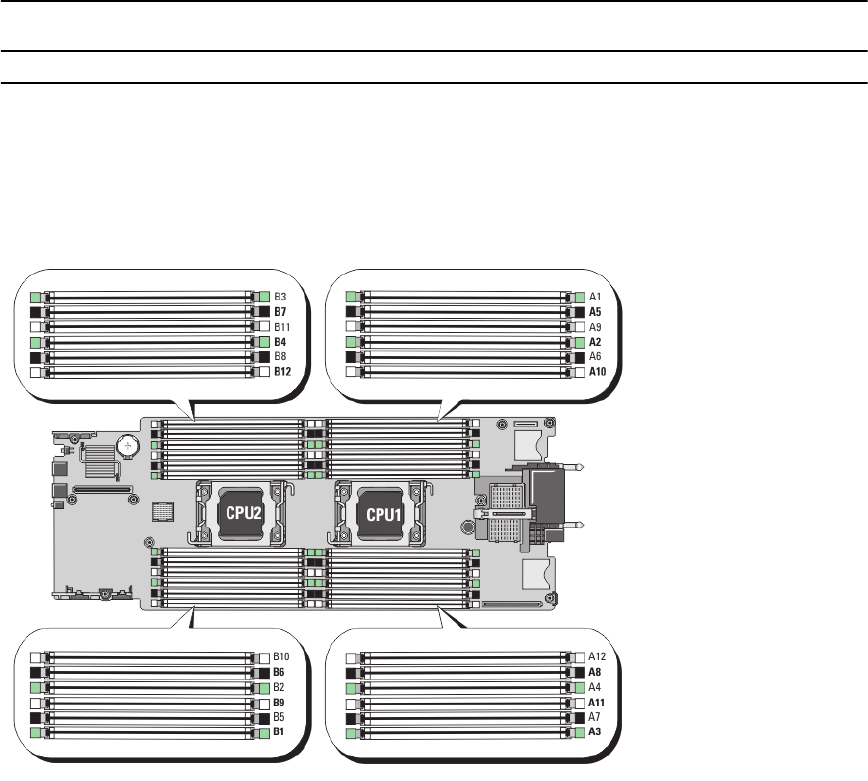
Figure 7. Memory Socket Locations
Memory channels are organized as follows:
Processor 1 channel 0: memory sockets A2, A6, and A10
channel 1: memory sockets A1, A5, and A9
channel 2: memory sockets A4, A8, and A12
channel 3: memory sockets A3, A7, and A11
Processor 2 channel 0: memory sockets B2, B6, and B10
channel 1: memory sockets B1, B5, and B9
channel 2: memory sockets B4, B8, and B12
channel 3: memory sockets B3, B7, and B11
31