
Computer Hardware User Manual


Table Of Contents
- Contents
- About Your System
- Using The System Setup And Boot Manager
- Installing Blade Components
- Recommended Tools
- Removing And Installing A Blade
- Opening And Closing The Blade
- Inside The Blade
- Cooling Shroud
- System Memory
- I/O Module Mezzanine Cards
- Management Riser Card
- SD vFlash Card
- Network Daughter Card/LOM Riser Card
- Processors
- Hard Drives/SSDs
- Hard-Drive/SSD Backplane
- System Board
- NVRAM Backup Battery
- Storage Controller Card
- Troubleshooting Your System
- Using System Diagnostics
- Jumpers And Connectors
- Technical Specifications
- System Messages
- Getting Help
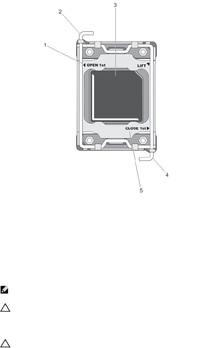
Figure 15. Processor Shield Opening and Closing Lever Sequence
1. OPEN 1st label
2. open first lever
3. processor
4. close first lever
5. CLOSE 1st label
9. Hold the tab on the processor shield and rotate it upward and out of the way.
10. If applicable, remove the socket protective cap from the processor shield. To remove the socket protective cap,
push the cap from the inside of the processor shield and move it away from the socket pins.
NOTE: It is recommended that you install/remove the socket protective cap from the processor shield with the
processor shield in the open position.
CAUTION: The socket pins are fragile and can be permanently damaged. Be careful not to bend the pins in the
socket when removing the processor out of the socket.
11. Lift the processor out of the socket and leave the release lever up so that the socket is ready for the new
processor.
CAUTION: If you are permanently removing a processor, you must install a socket protective cap and a processor/
DIMM blank in the vacant socket to ensure proper system cooling. The processor/DIMM blank covers the vacant
sockets for the DIMMs and the processor.
46