
Computer Hardware User Manual


Table Of Contents
- Contents
- About Your System
- Using The System Setup And Boot Manager
- Installing Blade Components
- Recommended Tools
- Removing And Installing A Blade
- Opening And Closing The Blade
- Inside The Blade
- Cooling Shroud
- System Memory
- I/O Module Mezzanine Cards
- Management Riser Card
- SD vFlash Card
- Network Daughter Card/LOM Riser Card
- Processors
- Hard Drives/SSDs
- Hard-Drive/SSD Backplane
- System Board
- NVRAM Backup Battery
- Storage Controller Card
- Troubleshooting Your System
- Using System Diagnostics
- Jumpers And Connectors
- Technical Specifications
- System Messages
- Getting Help
12. Remove the storage controller card/PCIe extender card.
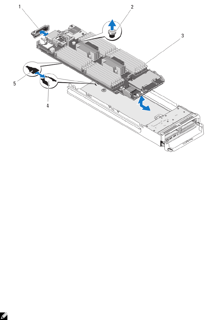
Figure 20. Removing and Installing the System Board
1. I/O connector cover
2. retention latch
3. system board
4. tabs on system chassis
5. slots in system board tray
Installing The System Board
1. Transfer the following components to the new system board:
– Internal USB key
– storage controller card/PCIe extender card
– SD vFlash card
– Memory modules and memory module blanks
– Processor(s) and heat sink(s), or processor filler blank
– network daughter card
2. Slide the new system board into the open end of the blade chassis until the retention latch or retention pin
engages.
NOTE: Ensure that the system board plate is parallel with the chassis.
When the board assembly is installed correctly, the tabs on the system board pan fit into the corresponding
openings in the floor of the blade chassis.
3. Replace the mezzanine card(s) in their original locations.
4. Reinstall the hard-drive/SSD backplane.
54