
Computer Hardware User Manual


Table Of Contents
- Contents
- About Your System
- Using The System Setup And Boot Manager
- Installing Blade Components
- Recommended Tools
- Removing And Installing A Blade
- Opening And Closing The Blade
- Inside The Blade
- Cooling Shroud
- System Memory
- I/O Module Mezzanine Cards
- Management Riser Card
- SD vFlash Card
- Network Daughter Card/LOM Riser Card
- Processors
- Hard Drives/SSDs
- Hard-Drive/SSD Backplane
- System Board
- NVRAM Backup Battery
- Storage Controller Card
- Troubleshooting Your System
- Using System Diagnostics
- Jumpers And Connectors
- Technical Specifications
- System Messages
- Getting Help
System Board Connectors
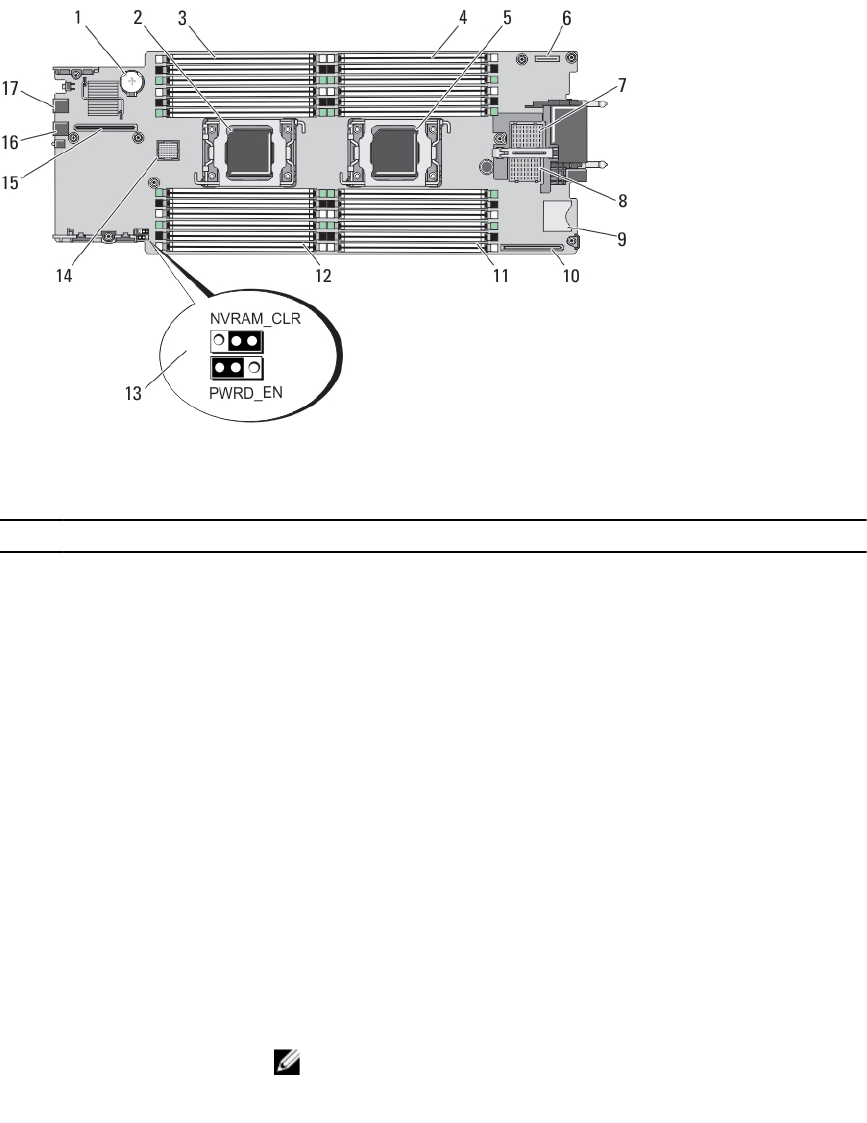
Figure 23. System Board Connectors
Table 4. System Board Connectors
Item Connector Description
1 BATTERY Connector for the 3.0 V coin cell battery
2 CPU2 Processor socket 2
3 B3, B7, B11, B4, B8, B12 Memory module sockets (for processor 2)
4 A1, A5, A9, A2, A6, A10 Memory module sockets (for processor 1)
5 CPU1 Processor socket 1
6 MANAGEMENT RISER Management riser card connector
7 MEZZ1_FAB_C Mezzanine card connector for Fabric C
8 MEZZ2_FAB_B Mezzanine card connector for Fabric B
9 vFLASH SD vFlash card connector
10 NETWORK DAUGHTER
CARD
Network daughter card connector
11 A3, A7, A11, A4, A8, A12 Memory module sockets (for processor 1)
12 B1, B5, B9, B2, B6, B10 Memory module sockets (for processor 2)
13 PWRD_EN, NVRAM_CLR
System configuration jumpers
NOTE: Access requires removal of system board.
14 HD_BP Hard-drive/SSD backplane connector
66