
Computer Hardware User Manual


Table Of Contents
- Contents
- About Your System
- Using The System Setup And Boot Manager
- Installing Blade Components
- Recommended Tools
- Removing And Installing A Blade
- Opening And Closing The Blade
- Inside The Blade
- Cooling Shroud
- System Memory
- I/O Module Mezzanine Cards
- Management Riser Card
- SD vFlash Card
- Network Daughter Card/LOM Riser Card
- Processors
- Hard Drives/SSDs
- Hard-Drive/SSD Backplane
- System Board
- NVRAM Backup Battery
- Storage Controller Card
- Troubleshooting Your System
- Using System Diagnostics
- Jumpers And Connectors
- Technical Specifications
- System Messages
- Getting Help
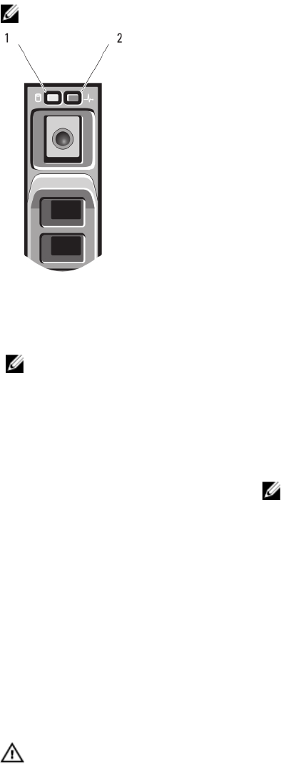
Hard-Drive/SSD Indicator Patterns
The hard-drive/SSD indicators display different patterns as drive events occur in the system.
NOTE: The blade must have a hard drive/SSD or a hard-drive blank installed in each drive bay.
Figure 2. Hard-Drive/SSD Indicators
1. drive activity indicator (green)
2. drive status indicator (green and amber)
NOTE: If the drive is in Advanced Host Controller Interface (AHCI) mode, the status LED (on the right side) does not
function and remains off.
Drive-Status Indicator Pattern Condition
Blinks green two times per second Identifying drive or preparing for removal
Off Drive ready for insertion or removal
NOTE: The drive status indicator remains off until all drives are
initialized after system power is applied. Drives are not ready
for insertion or removal during this time.
Blinks green, amber, and off Drive predicted failure
Blinks amber four times per second Drive failed
Blinks green slowly Drive rebuilding
Steady green Drive online
Blinks green three seconds, amber three
seconds, and off six seconds
Rebuild aborted
Other Information You May Need
WARNING: See the safety and regulatory information that shipped with your system. Warranty information may be
included within this document or as a separate document.
8