Dell PowerEdge VRTX, M820, M620, and M520 Getting Started Guide Regulatory Model: E22S, HHB, and FHB Regulatory Type: E22S001, HHB, and FHB007 Series
Notes, Cautions, and Warnings NOTE: A NOTE indicates important information that helps you make better use of your computer. CAUTION: A CAUTION indicates either potential damage to hardware or loss of data and tells you how to avoid the problem. WARNING: A WARNING indicates a potential for property damage, personal injury, or death. Copyright © 2014 Dell Inc. All rights reserved. This product is protected by U.S. and international copyright and intellectual property laws.
Installation And Configuration WARNING: Before performing the following procedure, review the safety instructions that came with the server module or enclosure. Unpacking The System WARNING: Whenever you need to lift the system, get others to assist you. To avoid injury, do not attempt to lift the system by yourself. Unpack the enclosure and the server module(s) and identify each item.
Figure 2. Extending the Feet of the Tower System Optional — Rack Configuration If you are using the optional rack configuration, assemble the rails and install the system in the rack following the safety instructions and the rack installation instructions provided with your system. NOTE: For more information on converting the system to rack mode, see the Dell PowerEdge VRTX Owner's Manual at dell.com/poweredgemanuals.
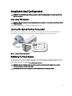
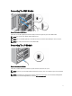
Connecting The CMC Module Figure 4. Connecting the CMC Module Connect the serial cable (optional) and network cable(s) from the management system to the CMC module. NOTE: Your system comes with the CMC installed in slot 1. NOTE: If the second CMC (optional) is not installed, connect the network cable to CMC port 1 on the enclosure. NOTE: The serial port connects to the active CMC module. Connecting The I/O Module Figure 5.
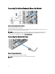
Connecting The Optional Keyboard, Mouse, And Monitor Figure 6. Connecting Keyboard, Mouse, and Monitor Connect the keyboard, mouse, and monitor. The connectors on the front of your system have icons indicating which cable to plug into each connector. Be sure to tighten the screws (if any) on the monitor's cable connector. NOTE: Connecting the keyboard, mouse, and monitor is optional. You can use the LCD menu options to map a server module to the KVM.
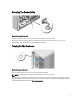
Securing The Power Cable Figure 8. Securing the Power Cable Bend the system power cable, as shown in the illustration, and attach to the cable strap. Plug the other end of the power cable into a grounded electrical outlet or a separate power source, such as an uninterruptible power supply (UPS) or a power distribution unit (PDU). Turning On The Enclosure Figure 9. Turning on the Enclosure Press the power button on the enclosure. The power indicator should light.
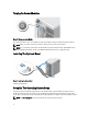
Turning On Server Modules Figure 10. Turning on a Server Module Press the power button on each server module, or power on the modules using the systems management software. NOTE: Make sure that the enclosure is powered on before you power on the server modules. NOTE: The server modules do not power on until the CMC is properly configured and has fully initialized. It may take an additional two minutes for the server iDRAC to initialize after the chassis is fully powered on.
Dell Software License Agreement Before using your system, read the Dell Software License Agreement that came with your system. You must consider any media of Dell-installed software as BACKUP copies of the software installed on your system’s hard drive. If you do not accept the terms of the agreement, call the customer assistance telephone number. For customers in the United States, call 800-WWW-DELL (800-999-3355). For customers outside the United States, see dell.
Model number: HHB Supply voltage: 12 V CC Current consumption: 37 A Model number: FHB Supply voltage: 12 V CC Current consumption: 75 A Technical Specifications Power AC power supply (per power supply unit) Wattage 1100 W Connector IEC C14 Heat dissipation 4100 BTU/hr maximum NOTE: Heat dissipation is calculated using the power supply wattage rating.
Physical — Server Modules Width 5.03 cm (1.98 inch) Depth 54.43 cm (21.43 inch) with handle closed 56.49 cm (22.24 inch) with handle open Weight (maximum) 5.50 kg (12.11 lb) NOTE: For additional specifications, see the server module's Owner's Manual at dell.com/poweredgemanuals. Physical — Enclosure Tower Configuration Height 48.44 cm (19.07 inch) with system feet 46.38 (cm) (18.26 inch) without system feet Width 21.92 cm (8.62 inch) without system feet 30.96 cm (12.
Environmental Temperature Ranges (for altitude less than 950 m or 3117 ft) 10 °C to 35 °C (50 °F to 95 °F) with no direct sunlight on the equipment. Humidity Percentage Range 10% to 80% Relative Humidity (RH) with 26 °C (78.8 °F) maximum dew point. Relative Humidity Storage 5% to 95% RH with 33 °C (91 °F) maximum dew point. Atmosphere must be non-condensing at all times. Maximum Vibration Operating 0.26 Grms at 5 Hz to 350 Hz (all operation orientations). Storage 1.
Environmental NOTE: Applies to data center and non-data center environments. Corrosive Dust • NOTE: Applies to data center and non-data center • environments. Air must be free of corrosive dust. Residual dust present in the air must have a deliquescent point less than 60% relative humidity. Gaseous Contamination NOTE: Maximum corrosive contaminant levels measured at ≤50% relative humidity. Copper Coupon Corrosion Rate <300 Å/month per Class G1 as defined by ANSI/ ISA71.04-1985.