Information Update Processor Installation w w w. d e l l . c o m | s u p p o r t . d e l l .
Notes, Cautions, and Warnings NOTE: A NOTE indicates important information that helps you make better use of your computer. CAUTION: A CAUTION indicates potential damage to hardware or loss of data if instructions are not followed. WARNING: A WARNING indicates a potential for property damage, personal injury, or death. ____________________ Information in this document is subject to change without notice. © 2009 Dell Inc. All rights reserved.
Information Update on Processor Installation Removing a Processor WARNING: Only trained service technicians are authorized to remove the system cover and access any of the components inside the system. Before you begin this procedure, review the safety instructions that came with the system. 1 Prior to upgrading your system, download the latest system BIOS version from support.dell.com and follow the instructions included in the compressed download file to install the update on your system.
Figure 1-1. Installing and Removing the Heat Sink 2 1 1 heat sink 2 release lever (2) NOTE: Your heat sink may appear differently than the one shown above. See your Hardware Owner’s Manual for a system-specific illustration. CAUTION: The processor is held in its socket under strong pressure. Be aware that the release lever can spring up suddenly if not firmly grasped.
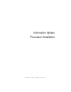
Figure 1-2. Removing a Processor 2 3 1 4 1 socket-release lever 2 processor 3 processor shield 4 ZIF socket CAUTION: Be careful not to bend any of the pins on the ZIF socket when removing the processor. Bending the pins can permanently damage the system board. 11 Carefully, lift the processor out of the socket and leave the release lever up so that the socket is ready for the new processor. After removing the processor, place it in an antistatic container for reuse, return, or temporary storage.
Installing a Processor WARNING: Only trained service technicians are authorized to remove the system cover and access any of the components inside the system. Before you begin this procedure, review the safety instructions that came with the system. NOTE: In a single-processor configuration, the CPU1 socket must be used. 1 If you are adding a second processor for the first time, remove the heatsink blank and the processor blank from the vacant processor socket.
Figure 1-3. Keeping the Processor Parallel to the Socket Figure 1-4.
Verify that the processor is properly aligned and seated. 9 Close the processor shield. See Figure 1-5. 10 Rotate the socket-release lever down until it snaps into place. See Figure 1-5. Figure 1-5. Installing a Processor 2 1 3 1 socket-release lever 3 processor shield 2 processor 11 Install the heat sink. NOTE: Your kit may contain a replacement heat sink if you are installing a processor that consumes additional power.
b Open the grease applicator included with your processor kit and apply all of the thermal grease in the applicator to the center of the topside of the new processor. c Place the heat sink on the processor. See Figure 1-1. d Close the heat-sink release levers or replace the screws at the corners of the heat sink. See your Hardware Owner’s Manual for a systemspecific illustration. See Figure 1-1. 12 Replace the cooling shroud. See "Installing the Cooling Shroud" in the Hardware Owner’s Manual.
Processor Installation
信息更新 处理器安装 w w w. d e l l . c o m | s u p p o r t . d e l l .
注、小心和警告 注:“注”表示可以帮助您更好地使用计算机的重要信息。 小心:“小心”表示如果不遵循说明,就有可能损坏硬件或导致数据 丢失。 警告: “警告”表示可能会造成财产损失、人身伤害甚至死亡。 ____________________ 本说明文件中的信息如有更改,恕不另行通知。 © 2009 Dell Inc.。版权所有,翻印必究。 未经 Dell Inc. 书面许可,严禁以任何形式复制这些材料。 本文中使用的商标:Dell 和 DELL 徽标是 Dell Inc. 的商标。 本说明文件中述及的其它商标和产品名称是指拥有相应商标和产品名称的公司或其制造的 产品。Dell Inc. 对本公司的商标和产品名称之外的其它商标和产品名称不拥有任何专有权。 2009 年 4 月 Rev.
有关处理器安装的信息更新 卸下处理器 警告:只有经过培训的维修技术人员才能卸下系统护盖并拆装系统内部的 任何组件。开始执行该步骤之前,请查看系统附带的安全说明。 1 在升级系统之前,请先从 support.dell.
图 1-1.
图 1-2.
安装处理器 警告:只有经过培训的维修技术人员才能卸下系统护盖并拆装系统内部的 任何组件。开始执行该步骤之前,请查看系统附带的安全说明。 注:在单处理器配置中,必须使用 CPU1 插槽。 1 如果是第一次添加第二个处理器,请先卸除空处理器插槽中的散热 器挡片和处理器挡片。卸下挡片的方法与卸下处理器相似。请参阅 “卸下处理器”。 2 通过仅触摸处理器的边缘,从包装材料中取出处理器。请勿触摸处理 器的底部。小心地用手指握住处理器的侧边缘。将处理器移动到系统 中时,手放在处理器下面。 3 找到系统板插槽中的插针 1 标记。 4 找到处理器顶部的插针 1 标记。处理器顶部的插针 1 标记显示为三 角形。请参阅图 1-4。 小心:处理器放置不正确会永久性地损坏系统板或处理器。请注意不要弯 曲插槽上的插针。 5 将处理器放在插槽上,使两个插针 1 对准并保持水平。请参阅图 1-3 和 图 1-4。 小心:请勿强行插入处理器。如果处理器的位置正确,它会顺利卡入 插槽。 6 将处理器的槽口与 ZIF 插槽中的插槽卡锁对准。请参阅图 1-4。 7 将处理器安装到插槽中。使处理器保持水平(请参阅图 1-3)并将其 竖直向下插入
图 1-3. 使处理器保持与插槽平行 图 1-4.
8 检查处理器是否已正确对准并就位。 9 合上处理器护盖。请参阅图 1-5。 10 向下转动插槽释放拉杆,直至其卡入到位。请参阅图 1-5。 图 1-5.
12 装回冷却导流罩。请参阅《硬件用户手册》中的“安装冷却导 流罩”。 13 合上系统护盖。请参阅《硬件用户手册》中的“合上系统护盖”。 14 将系统和外围设备重新连接至各自的电源插座,并打开系统。 15 按 键进入系统设置程序,并检查处理器信息是否与新的系统配置 相匹配。请参阅《硬件用户手册》中的“进入系统设置程序”。 16 运行系统诊断程序,验证新处理器是否可以正常运行。 17 请参阅《硬件用户手册》中的“运行系统诊断程序”以了解关于运行 诊断程序的信息。 处理器安装 19
处理器安装
Mise à jour des informations Installation du processeur w w w. d e l l . c o m | s u p p o r t . d e l l .
Remarques, précautions et avertissements REMARQUE : Une REMARQUE indique des informations importantes qui peuvent vous aider à mieux utiliser votre ordinateur. PRÉCAUTION : Une PRÉCAUTION vous avertit d'un risque de dommage matériel ou de perte de données en cas de non-respect des instructions données. AVERTISSEMENT : Un AVERTISSEMENT vous avertit d'un risque d'endommagement du matériel, de blessure corporelle ou de mort.
Mise à jour des informations sur l'installation du processeur Retrait d'un processeur AVERTISSEMENT : Seuls les techniciens de maintenance qualifiés sont habilités à retirer le capot du système pour accéder aux composants internes. Avant de commencer cette procédure, lisez les consignes de sécurité fournies avec le système. 1 Avant de mettre à niveau votre système, téléchargez la dernière version du BIOS du système à partir du site support.dell.com.
7 Actionnez l'autre levier du dissipateur de chaleur. 8 Dégagez délicatement le dissipateur de chaleur du processeur, puis posezle de côté, face enduite de pâte thermique vers le haut. Figure 1-1. Installation et retrait du dissipateur de chaleur 2 1 1 dissipateur de chaleur 2 levier d'éjection (2) REMARQUE : Le dissipateur de chaleur de votre ordinateur peut être différent du modèle représenté ci-dessus. Pour une illustration spécifique à votre système, voir le Manuel du propriétaire.
9 Avec le pouce, appuyez fermement sur le levier d'éjection du support du processeur, puis déverrouillez-le en exerçant une pression pour l'extraire de dessous la patte. Faites pivoter le levier d'éjection de 90 degrés jusqu'à ce que le processeur sorte de son support. Voir figure 1-2. 10 Tenez le cadre de protection du processeur par sa languette afin de le redresser et de dégager l'accès au processeur. Voir figure 1-2. Figure 1-2.
Si vous retirez définitivement le processeur, vous devez installer un cache de processeur et un cache de dissipateur de chaleur dans le support CPU2 afin d'assurer un refroidissement correct du système. La procédure d'insertion des caches est similaire à l'installation d'un processeur. Voir “Installation d'un processeur”. Installation d'un processeur AVERTISSEMENT : Seuls les techniciens de maintenance qualifiés sont habilités à retirer le capot du système pour accéder aux composants internes.
6 Alignez les encoches du processeur sur les repères du support ZIF. Voir figure 1-4. 7 Installez le processeur dans le support. Maintenez-le en position horizontale (voir figure 1-3) en l'insérant dans le support. Le processeur doit être en position flottante sur les broches. Il sera maintenu en place par son cadre de protection. Figure 1-3.
Figure 1-4. Alignement du processeur sur les repères du support 3 2 4 1 5 7 6 1 levier d'éjection du support 2 processeur 3 cadre de protection du processeur 4 encoche du processeur (2) 5 repère (2) 6 support ZIF 7 indicateurs de broche 1 (2) 8 Vérifiez que le processeur est correctement aligné et installé. 9 Refermez le cadre de protection du processeur. Voir figure 1-5. 10 Abaissez le levier d'éjection du support jusqu'à ce qu'il s'enclenche. Voir figure 1-5.
Figure 1-5. Installation d'un processeur 2 1 3 1 levier d'éjection du support 3 cadre de protection du processeur 2 processeur 11 Installez le dissipateur de chaleur. REMARQUE : Votre kit peut contenir un dissipateur de chaleur de rechange utilisable en cas d'installation d'un processeur qui consomme plus d'énergie. Le nouveau dissipateur de chaleur peut être différent de l'ancien ; néanmoins, vous devez l'utiliser car il offre de meilleures caractéristiques de dissipation thermique.
12 Réinstallez le carénage de refroidissement. Voir la section “Installing the Cooling Shroud” (Installation du carénage de refroidissement) du Manuel du propriétaire. 13 Refermez le système. Voir la section “Closing the System” (Fermeture du système) du Manuel du propriétaire. 14 Rebranchez le système et les périphériques aux prises secteur, puis allumez le système.
Aktuelle Informationen Prozessorinstallation w w w. d e l l . c o m | s u p p o r t . d e l l .
Anmerkungen, Vorsichtshinweise und Warnungen ANMERKUNG: Eine ANMERKUNG macht auf wichtige Informationen aufmerksam, mit denen Sie das System besser einsetzen können. VORSICHTSHINWEISE: Mit einem VORSICHTSHINWEISE werden Sie auf mögliche Gefahrenquellen hingewiesen, die Hardwareschäden oder Datenverlust zur Folge haben können, wenn die Anweisungen nicht befolgt werden.
Aktuelle Informationen zur Prozessorinstallation Entfernen eines Prozessors WARNUNG: Nur ausgebildete Service-Techniker dürfen die Gehäuseabdeckung entfernen und auf die Komponenten im Inneren des Systems zugreifen. Lesen Sie die Sicherheitshinweise, die Sie mit dem System erhalten haben, bevor Sie mit dem Ein- oder Ausbau beginnen. 1 Bevor Sie ein Systemupgrade durchführen, laden Sie die aktuelle SystemBIOS-Version von support.euro.dell.com herunter.
7 Lösen Sie den anderen Kühlkörper-Entriegelungshebel. 8 Heben Sie den Kühlkörper vorsichtig vom Prozessor ab, und legen Sie ihn mit der Oberseite nach unten ab (Wärmeleitpaste nach oben). Abbildung 1-1. Kühlkörper installieren und entfernen 2 1 1 Kühlkörper 2 Entriegelungshebel (2) ANMERKUNG: Der Kühlkörper Ihres Systems kann anders aussehen als der oben abgebildete. Eine systemspezifische Abbildung finden Sie im HardwareBenutzerhandbuch.
9 Legen Sie Ihren Daumen fest auf den Freigabehebel des Prozessorsockels und lösen Sie den Hebel aus der verriegelten Position, indem Sie ihn nach unten drücken und unter der Lasche hervorziehen. Schwenken Sie den Freigabehebel um 90 Grad nach oben, bis der Prozessor vom Sockel gelöst ist. Siehe Abbildung 1-2. 10 Drehen Sie die Prozessorabdeckung mithilfe der Lasche nach oben und aus dem Weg. Siehe Abbildung 1-2. Abbildung 1-2.
11 Heben Sie den Prozessor vorsichtig aus dem Sockel, und belassen Sie den Hebel in senkrechter Position, damit der neue Prozessor in den Sockel eingepasst werden kann. Legen Sie den Prozessor nach dem Herausnehmen in einen antistatischen Behälter, um ihn später wieder einzusetzen, zurückzusenden oder zeitweilig zu lagern. Berühren Sie nicht die Unterseite des Prozessors. Fassen Sie den Prozessor nur an den Kanten an.
5 Positionieren Sie den Prozessor so über dem Sockel, dass die beiden Stift1-Markierungen miteinander ausgerichtet und parallel sind. Siehe Abbildung 1-3 und Abbildung 1-4. VORSICHTSHINWEISE: Wenden Sie beim Einsetzen des Prozessors keine Kraft an. Wenn der Prozessor korrekt positioniert ist, lässt er sich leicht in den Sockel einsetzen. 6 Richten Sie die Kerben am Prozessor mit den Passungen am ZIF-Sockel aus. Siehe Abbildung 1-4. 7 Setzen Sie den Prozessor in den Sockel ein.
Abbildung 1-4. Ausrichten des Prozessors mit den Sockelpassungen 3 2 4 1 5 7 6 1 Freigabehebel des Sockels 2 Prozessor 3 Prozessorabdeckung 4 Prozessorkerbe (2) 5 Sockelpassung (2) 6 ZIF-Sockel 7 Stift-1-Markierungen (2) 8 Überprüfen Sie, ob der Prozessor richtig ausgerichtet und eingesetzt ist. 9 Schließen Sie die Prozessorabdeckung. Siehe Abbildung 1-5. 10 Schwenken Sie den Freigabehebel des Sockels nach unten, bis er einrastet. Siehe Abbildung 1-5.
Abbildung 1-5. Installieren eines Prozessors 2 1 3 1 Freigabehebel des Sockels 3 Prozessorabdeckung 2 Prozessor 11 Installieren Sie den Kühlkörper. ANMERKUNG: Das Prozessor-Kit enthält möglicherweise einen Austauschkühlkörper, wenn Sie einen Prozessor einbauen, der zusätzliche Energie verbraucht. Der neue Kühlkörper sieht eventuell nicht anders aus der ursprüngliche Kühlkörper, er weist jedoch verbesserte Spezifikationen für die Wärmeabgabe auf und muss deshalb verwendet werden.
12 Setzen Sie die Kühlkörperabdeckung auf. Siehe „Installieren des Kühlgehäuses“ im Hardware-Benutzerhandbuch. 13 Schließen Sie das System. Siehe „Schließen des Systems“ im HardwareBenutzerhandbuch. 14 Verbinden Sie das System und die Peripheriegeräte wieder mit dem Netzstrom und schalten Sie sie ein. 15 Drücken Sie , um das System-Setup-Programm aufzurufen, und überprüfen Sie, ob die Prozessorinformationen mit der neuen Systemkonfiguration übereinstimmen.
アップデート情報 プロセッサの取り付け w w w. d e l l . c o m | s u p p o r t . d e l l .
メモ、注意、警告 メモ:コンピュータを使いやすくするための重要な情報を説明してい ます。 注意:手順に従わない場合は、ハードウェアの損傷やデータの損失の可能 性があることを示しています。 警告: 物的損害、けが、または死亡の原因となる可能性があることを示 しています。 ____________________ 本書の内容は予告なく変更されることがあります。 © 2009 すべての著作権は Dell Inc. にあります。 Dell Inc. の書面による許可のない複製は、いかなる形態においても厳重に禁じられてい ます。 本書に使用されている商標:Dell および DELL ロゴは Dell Inc. の商標です。 商標または製品の権利を主張する事業体を表すためにその他の商標および社名が使用され ていることがあります。Dell Inc. はデル以外の商標や社名に対する所有権を一切否認し ます。 2009 年 4 月 Rev.
プロセッサの取り付けに関するアップデート 情報 プロセッサの取り外し 警告:システムのカバーを取り外して内部の部品に手を触れる作業は、 トレーニングを受けたサービス技術者のみが行ってください。システム に付属のマニュアルの「安全にお使いいただくために」を参照してから、 本項の作業を開始してください。 1 システムをアップグレードする前に、support.dell.
7 もう 1 つのヒートシンクリリースレバーを外します。 8 ヒートシンクをプロセッサから注意深く持ち上げ、裏返し(サーマ ルグリースが付いた側を上)にして取っておきます。 図 1-1.
9 プロセッサのソケットリリースレバーを親指で押し下げてタブの下 から引き出し、レバーをロック位置から外します。レバーを上方向 に 90 度持ち上げて、プロセッサをソケットから外します。図 1-2 を 参照してください。 10 プロセッサシールドのタブを持ち、シールドを上方向に開いて、 プロセッサが取り出せる状態にします。図 1-2 を参照してください。 図 1-2.
11 プロセッサをソケットから慎重に取り外し、ソケットに新しいプロ セッサを取り付けられるように、リリースレバーは立てたままにし ておきます。 プロセッサを取り外したら、再利用、返品、または一時的な保管の ために、静電気防止パッケージに入れます。プロセッサの底部に触 れないでください。プロセッサは側面の端以外に触れないでくだ さい。 プロセッサを取り外したままにする場合は、システムの正常な冷却 状態を維持するために、プロセッサのダミーとヒートシンクのダ ミーを CPU2 ソケットに取り付ける必要があります。ダミーの取り 付け方は、プロセッサの取り付けと同様です。「プロセッサの取り付 け」を参照してください。 プロセッサの取り付け 警告:システムのカバーを取り外して内部の部品に手を触れる作業は、 トレーニングを受けたサービス技術者のみが行ってください。システムに 付属のマニュアルの「安全にお使いいただくために」を参照してから、 本項の作業を開始してください。 メモ:シングルプロセッサ構成では、必ず CPU1 ソケットを使用してくだ さい。 1 セカンドプロセッサを初めて増設する場合は、ヒートシンクのダ ミ
5 ピン 1 同士を合わせ、プロセッサをソケットに水平に置きます。 図 1-3 および 図 1-4 を参照してください。 注意:プロセッサは強く押し込まないでください。プロセッサの位置が 合っていれば、簡単にソケットに入ります。 6 プロセッサの切り込みを ZIF ソケットのソケットキーに合わせ ます。図 1-4 を参照してください。 7 プロセッサをソケットに取り付けます。プロセッサを水平に保ち (図 1-3 を参照)、ソケットにまっすぐに挿入します。プロセッ サは、プロセッサシールドで所定の位置に固定できるように、ピン を合わせて軽く載せます。 図 1-3.
図 1-4.
図 1-5.
12 冷却用エアフローカバーを取り付けます。『ハードウェアオーナーズ マニュアル』の「冷却用エアフローカバーの取り付け」を参照して ください。 13 システムカバーを閉じます。『ハードウェアオーナーズマニュアル』 の「システムカバーの取り付け」を参照してください。 14 システムおよび周辺機器を電源コンセントに接続し、システムの電 源をオンにします。 15 を押してセットアップユーティリティを起動し、プロセッサの情 報が新しいシステム設定と一致していることを確認します。『ハード ウェアオーナーズマニュアル』の「セットアップユーティリティの 使い方」を参照してください。 16 システム診断プログラムを実行し、新しいプロセッサが正しく動作 することを確認します。 17 Diagnostics(診断)の実行方法については、『ハードウェアオーナー ズマニュアル』の「システム診断プログラムの実行」を参照してく ださい。 50 プロセッサの取り付け
설명서 갱신본 프로세서 설치 w w w. d e l l . c o m | s u p p o r t . d e l l .
주, 주의 및 경고 주: "주"는 컴퓨터를 보다 효율적으로 사용하는 데 도움을 주는 중요 정보를 제 공합니다. 주의: "주의"는 지침을 준수하지 않을 경우의 하드웨어 손상이나 데이터 손실 위험을 설명합니다. 경고 : " 경고 " 는 재산상의 피해나 심각한 부상 또는 사망을 유발할 수 있는 위험이 있음을 알려줍니다 . ____________________ 이 문서의 정보는 사전 통보 없이 변경될 수 있습니다. © 2009 Dell Inc. 저작권 본사 소유. Dell Inc.의 서면 승인 없이 어떠한 경우에도 무단 복제하는 것을 엄격히 금합니다. 본 설명서에 사용된 상표인 Dell 및 DELL 로고는 Dell Inc.의 상표입니다. 본 문서에서 특정 회사의 표시나 제품 이름을 지칭하기 위해 기타 상표나 상호를 사용할 수도 있습니다. Dell Inc.는 자사가 소유하고 있는 것 이외에 기타 모든 상표 및 상호에 대한 어떠한 소유권도 없습니다. 2009년 4월 Rev.
프로세서 설치에 대한 설명서 갱신본 프로세서 분리 경고 : 숙련된 서비스 기술자만 시스템 덮개를 분리하고 시스템 내부의 구성 요소에 액세스해야 합니다 . 이 절차를 시작하기 전에 시스템과 함께 제공된 안전 지침을 검토하십시오 . 1 시스템을 업그레이드하기 전에 support.dell.com 에서 최신 버전의 시 스템 BIOS 를 다운로드한 다음 압축된 다운로드 파일에 포함된 지침 에 따라 업데이트를 시스템에 설치합니다 . 2 시스템과 시스템에 장착된 모든 주변 장치의 전원을 끄고 전원 콘센트 에서 시스템을 분리합니다 . AC 전원에서 분리한 후 덮개를 분리하기 전에 시스템에서 저장된 전원이 완전히 방전되도록 전원 단추를 3 초 동 안 누르고 있습니다 . 주 : 시스템 내부의 구성요소를 다룰 때는 항상 정전기 방지 매트와 접지대를 사용하는 것이 좋습니다 . 3 시스템을 엽니다. 하드웨어 소유자 매뉴얼의 "시스템 열기"를 참조하십 시오 . 4 냉각기 덮개를 분리합니다 .
그림 1. 방열판 설치 및 분리 2 1 1 방열판 2 분리 레버 (2 개 ) 주 : 실제 방열판의 모양은 위와 다를 수 있습니다 . 시스템별 그림 설명은 하드웨 어 소유자 매뉴얼을 참조하십시오 . 주의 : 강한 힘으로 프로세서를 해당 소켓에 고정해야 합니다 . 단단히 잡지 않으면 분리 레버가 갑자기 튕겨 나올 수 있습니다 . 9 엄지 손가락을 프로세서 소켓 분리 레버 위에 놓고 아래로 누른 다음 탭 아래에서 밖으로 잡아당겨 레버를 잠금 위치에서 분리합니다 . 프로세 서가 소켓에서 분리될 때까지 레버를 90 도 각도로 위로 돌립니다 . 그림 2 를 참조하십시오 . 10 프로세서 실드의 탭을 사용하여 실드를 위로 돌려 꺼냅니다 . 그림 2 를 참조하십시오 .
그림 2. 프로세서 분리 2 3 1 4 1 소켓 분리 레버 2 프로세서 3 프로세서 실드 4 ZIF 소켓 주의 : 프로세서를 분리할 때 ZIF 소켓의 핀이 구부러지지 않도록 주의하십 시오 . 핀이 구부러지면 시스템 보드가 영구적으로 손상될 수 있습니다 . 11 프로세서를 소켓에서 조심스럽게 들어 꺼내고 분리 레버를 위로 돌린 상태로 두면 소켓에 새 프로세서를 설치할 준비가 됩니다 . 프로세서를 분리한 후 재사용, 반환 또는 임시 저장을 위해 정전기 방지 상자에 보관합니다 . 프로세서 하단은 만지지 마십시오 . 프로세서 측면 모서리만 만집니다 . 프로세서를 영구히 제거할 경우에는 프로세서 보호물과 방열판 보호물 을 CPU2 소켓에 설치하여 적절한 시스템 냉각을 확보해야 합니다 . 보 호물을 추가하는 것은 프로세서를 설치할 때와 유사합니다 . " 프로세서 설치 " 를 참조하십시오 .
프로세서 설치 경고 : 숙련된 서비스 기술자만 시스템 덮개를 분리하고 시스템 내부의 구성 요소에 액세스해야 합니다 . 이 절차를 시작하기 전에 시스템과 함께 제공된 안전 지침을 검토하십시오 . 주 : 단일 프로세서 구성에서는 CPU1 소켓을 사용해야 합니다 . 1 두 번째 프로세서를 처음으로 추가하는 경우에는 방열판 보호물을 분 리한 다음 빈 프로세서 소켓에서 프로세서 보호물을 분리합니다 . 보호 물을 분리하는 것은 프로세서를 분리할 때와 유사합니다 . " 프로세서 분리 " 를 참조하십시오 . 2 프로세서의 모서리만 잡아 포장재에서 프로세서를 분리합니다 . 프로세 서 하단은 만지지 마십시오 . 손가락으로 프로세서의 측면 모서리를 조 심스럽게 잡고 다룹니다 . 프로세서를 시스템으로 옮길 때에는 프로세 서 아래에 손을 놓습니다 . 3 시스템 보드 소켓에서 핀 1 표시를 찾습니다 . 4 프로세서 상단에서 핀 1 표시를 찾습니다. 핀 1 표시는 프로세서 상단에 삼각형으로 표시되어 있습니다 .
그림 3. 프로세서를 소켓과 평행하게 유지 그림 4.
8 프로세서가 제대로 맞추어 장착되어 있는지 확인합니다 . 9 프로세서 실드를 닫습니다 . 그림 5 를 참조하십시오 . 10 소켓 분리 레버가 제자리에 고정될 때까지 돌려 내립니다 . 그림 5 를 참조하십시오 . 그림 5. 프로세서 설치 1 1 소켓 분리 레버 3 프로세서 실드 2 3 2 프로세서 11 방열판을 설치합니다 . 주 : 추가 전원을 소모하는 프로세서를 설치할 경우 교체 방열판이 키트 에 포함되어 있을 수 있습니다 . 새 방열판은 원래 방열판과 다르게 보이 지 않을 수도 있지만 열 손실 사양이 개선되었으므로 반드시 사용해야 합니다 . a 깨끗하고 보풀이 없는 천을 사용하여 방열판에 묻어 있는 열 그리 즈를 닦아냅니다 . 주의 : 열 그리즈를 지나치게 많이 사용하면 여분의 그리즈가 프로세서 소켓 에 묻어 더러워질 수 있습니다 . b 58 프로세서 키트에 포함된 그리즈 주입기를 열고 주입기의 모든 열 그리즈를 새 프로세서 윗면의 가운데에 바릅니다 .
c 방열판을 프로세서에 놓습니다 . 그림 1 을 참조하십시오 . d 방열판 분리 레버를 닫거나 방열판 모서리의 나사를 다시 끼웁 니다 . 시스템별 그림 설명은 하드웨어 소유자 매뉴얼을 참조하십 시오 . 그림 1 을 참조하십시오 . 12 냉각 덮개를 장착합니다. 하드웨어 소유자 매뉴얼의 "냉각기 덮개 설치" 를 참조하십시오 . 13 시스템을 닫습니다. 하드웨어 소유자 매뉴얼의 "시스템 닫기"를 참조하 십시오 . 14 시스템 및 주변 장치를 전원 콘센트에 다시 연결하고 시스템을 켭니다 . 15 키를 눌러 시스템 설치 프로그램을 시작하고 프로세서 정보가 새 로운 시스템 구성과 일치하는지 확인합니다 . 하드웨어 소유자 매뉴 얼의 " 시스템 설치 프로그램 시작 " 을 참조하십시오 . 16 시스템 진단 프로그램을 실행하여 새 프로세서가 올바르게 작동하는지 확인합니다 .
프로세서 설치
Actualización de información Instalación del procesador w w w. d e l l . c o m | s u p p o r t . d e l l .
Notas, precauciones y avisos NOTA: Una NOTA proporciona información importante que le ayudará a utilizar mejor el ordenador. PRECAUCIÓN: Un mensaje de PRECAUCIÓN indica la posibilidad de daños en el hardware o la pérdida de datos si no se siguen las instrucciones. AVISO: Un mensaje de AVISO indica el riesgo de daños materiales, lesiones o incluso la muerte. ____________________ La información contenida en este documento puede modificarse sin previo aviso. © 2009 Dell Inc. Todos los derechos reservados.
Actualización de información sobre la instalación del procesador Extracción de un procesador AVISO: Los técnicos de servicio especializados son las únicas personas autorizadas para retirar las cubiertas y acceder a los componentes internos del sistema. Antes de iniciar este procedimiento, revise las instrucciones de seguridad incluidas con el sistema. 1 Antes de actualizar el sistema, descargue la versión más reciente del BIOS del sistema desde support.dell.
7 Suelte la otra palanca de liberación del disipador de calor. 8 Levante con cuidado el disipador de calor para extraerlo del procesador y déjelo a un lado boca abajo (con la parte de la pasta térmica hacia arriba). Ilustración 1-1. Instalación y extracción del disipador de calor 2 1 1 Disipador de calor 2 Palanca de liberación (2) NOTA: Es posible que su disipador de calor tenga un aspecto distinto del que se muestra más arriba.
9 Apriete con firmeza la palanca de liberación del zócalo del procesador con el pulgar y libérela de su posición de bloqueo. Para ello, presione hacia abajo y tire hacia fuera desde debajo de la lengüeta. Gire la palanca 90 grados hacia arriba hasta que el procesador se libere del zócalo. Vea la ilustración 1-2. 10 Utilice la lengüeta del protector del procesador para girar el protector hacia arriba y quitarlo del paso. Vea la ilustración 1-2. Ilustración 1-2.
11 Levante con cuidado el procesador para extraerlo del zócalo y deje la palanca de liberación hacia arriba de modo que el zócalo esté preparado para alojar el nuevo procesador. Tras extraer el procesador, colóquelo en un contenedor antiestático para utilizarlo posteriormente, devolverlo o almacenarlo de forma temporal. No toque la parte inferior del procesador. Toque únicamente los bordes laterales del procesador.
5 Coloque el procesador sobre el zócalo con cada pata 1 alineada y plana. Vea la ilustración 1-3 y la ilustración 1-4. PRECAUCIÓN: No emplee fuerza para colocar el procesador. Cuando el procesador está colocado de forma correcta, se encaja fácilmente en el zócalo. 6 Alinee las muescas del procesador con los salientes del zócalo ZIF. Consulte ilustración 1-4. 7 Instale el procesador en el zócalo. Mantenga el procesador en paralelo (vea la ilustración 1-3) e insértelo en el zócalo.
Ilustración 1-4. Alineación del procesador con los salientes del zócalo 3 2 4 1 5 7 6 1 Palanca de liberación del zócalo 2 Procesador 3 Protector del procesador 4 Muesca del procesador (2) 5 Saliente del zócalo (2) 6 Zócalo ZIF 7 Indicadores de la pata 1 (2) 8 Asegúrese de que el procesador esté alineado e insertado correctamente. 9 Cierre el protector del procesador. Vea la ilustración 1-5. 10 Gire la palanca de liberación del zócalo hacia abajo hasta que se asiente en su lugar.
Ilustración 1-5. Instalación de un procesador 2 1 3 1 Palanca de liberación del zócalo 3 Protector del procesador 2 Procesador 11 Instale el disipador de calor. NOTA: Puede que el kit contenga un disipador de calor de repuesto, si va a instalar un procesador que consume energía adicional. Es posible que el aspecto del nuevo disipador de calor no difiera del original; sin embargo, cuenta con especificaciones de disipación térmica mejoradas y se debe utilizar.
12 Vuelva a colocar la cubierta de refrigeración. Consulte “Instalación de la cubierta de refrigeración” en el Manual del propietario del hardware. 13 Cierre el sistema. Consulte “Cierre del sistema” en el Manual del propietario del hardware. 14 Vuelva a conectar el sistema y los periféricos a las tomas eléctricas y, a continuación, encienda el sistema.