
Owners Manual

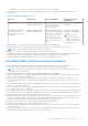
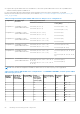
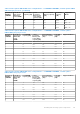
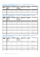
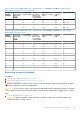
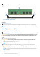
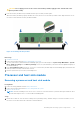
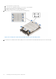
Table Of Contents
- Dell EMC PowerEdge MX750c Installation and Service Manual
- Contents
- About this document
- Dell EMC PowerEdge MX750c system overview
- Initial system setup and configuration
- Minimum to POST and system management configuration validation
- Installing and removing system components
- Safety instructions
- Before working inside your system
- After working inside your system
- Recommended tools
- PowerEdge MX750c sled
- Sled cover
- Air shroud
- Processor and memory module blank
- Drives
- Drive backplane
- Cable routing
- Drive cage
- Control panel
- System memory
- Processor and heat sink module
- PERC card
- Optional IDSDM module
- M.2 BOSS card
- Mezzanine cards
- Optional internal USB memory key
- System battery
- System board
- Trusted Platform Module
- Upgrade Kits
- Jumpers and connectors
- System diagnostics and indicator codes
- Getting help
- Documentation resources

Table 27. Intel Optane PMem 200 Series Configuration 5 - 8 x RDIMMs/ LRDIMMs, 8 x Intel Optane
PMem 200 Series per processor (continued)
Total No of
RDIMMs /
LRDIMMs
Total No of
Intel Optane
PMem 200
Series
DIMMs
1 R/LRDIMM
capacity (GB)
1 Intel
Persistent
Memory 200
series (BPS)
capacity (GB)
Total Standard
Memory Capacity
(GB)
Total PM
Capacity
(GB)
Supported Modes
8 8 16 512 128 4096 AD
8 8 32 512 256 4096 MM or AD
8 8 64 512 512 4096 MM or AD
8 8 128 512 1024 4096 MM or AD
Table 28. Intel Optane PMem 200 Series Configuration 6 - 12 x RDIMMs/ LRDIMMs, 2 x Intel Optane
PMem 200 Series per processor
Total No of
RDIMMs /
LRDIMMs
Total No of
Intel Optane
PMem 200
Series
DIMMs
1 R/LRDIMM
capacity (GB)
1 Intel
Persistent
Memory 200
series (BPS)
capacity (GB)
Total Standard
Memory Capacity
(GB)
Total PM
Capacity
(GB)
Supported Modes
12 2 16 128 192 256 AD
12 2 32 128 384 256 AD
12 2 64 128 768 256 AD
12 2 128 128 1536 256 AD
12 2 16 256 192 512 AD
12 2 32 256 384 512 AD
12 2 64 256 768 512 AD
12 2 128 256 1536 512 AD
12 2 16 512 192 1024 AD
12 2 32 512 384 1024 AD
12 2 64 512 768 1024 AD
12 2 128 512 1536 1024 AD
Removing a memory module
Prerequisites
1. Follow the safety guidelines listed in Safety instructions.
2. Follow the procedure listed in Before working inside your system.
3. Remove the air shroud.
WARNING:
The memory modules are hot to touch for some time after the system has been powered off. Allow
the memory modules to cool before handling them.
CAUTION: To ensure proper system cooling, memory module blanks must be installed in any memory socket that
is not populated. Remove memory module blanks only if you intend to install memory modules in those sockets.
Steps
1. Locate the appropriate memory module socket.
CAUTION:
Handle each memory module only by the card edges, ensuring not to touch the middle of the
memory module or metallic contacts.
Installing and removing system components 57